


4 Replacement Procedures 4.1 General
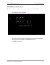
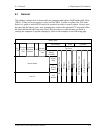
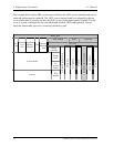
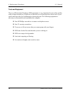
The example below shows FRUs to be removed before the LED / power button board can be
removed and repaired or replaced. The LED / power button board is overlapped by the top
cover which must be removed before the LED / power button board can be reached. The top
cover is in turn overlapped by the removable main module, HDD and keyboard. Always
starts the disassembly process by removing the battery pack.
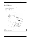
Battery pack
Main Module HDD Keyboard
Top Cover
PC
Card
Wireless
LAN
Unit
Expansion
Memory
Module
CPU
Modem /
Bluetooth
Unit
Display
Assembly
Display
Mask
System Board
FL
Inverter
Board
Fan Set
LCD
Module
Direct Play Button Board
CIR Board
Audio Board
Speakers
LED / Power Button Board
Function Key Board
TouchPad
4-2 Satellite P20-25 Series Maintenance Manual