


Users Manual TOPAS900 Flash V2.1
HWU Elektronik Oberhausen Page 10
3. Hardware Description
TOPAS900 Flash consists of two boards: Programming-and-Debugging Board and Flash
Carrier Board.
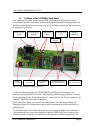
3.1. Programming and Debugging Board
As the name betrays this board is for programming and debugging purposes. The
firmware processor, a TMP87P808P, is listening the serial data communication between a
PC and the TOPAS900 Flash board. The firmware reacts on special data sequences to
switch the target processor to several modes.
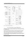
The Programming and Debugging is composed of the following components (to understand the
design in detail it is recommended to make a print out of the schematics shown at the end of this
manual):
• Firmware Processor
• Power supply
• Status LEDs
• Control Switches (Reset and NMI)
• Serial Communication, Connector and Line Driver
• Connector to Flash Carrier Board
3.1.1. Firmware Processor
A Toshiba TMP87P808 8-bit microcontroller of the TLCS-870 family is used. It is driven
by an 8 MHz quartz resonator.
The processor drives control lines of the target system (Flash Carrier Board with
TMP95FY64). The lines are /EA, /BOOT and /RESET. With these lines the target
processor can de driven into several modes that are selected by the rising edge of the
RESET input. Please refer to the manual for further information on Single Boot Mode /
Single Chip Mode and Multi Chip Mode. Also read the information given by the
memory maps later in this manual.
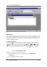
To control the target system the firmware is listening to the serial communication for
certain binary control sequences that are generated by the Windows-based Flash
Programming Tool. If a control sequence match is detected, the firmware processor
switches the target system into the required mode.
3.1.2. Power Supply
The power supply is mainly build by the net plug and a 5V voltage regulator. Because the
board has no on/off switch unplug the power plug from the board when connecting or
disconnecting the target or when connecting the Flash Carrier Board to another
application. The input power (at the board’s power plug) can be up to 12 V DC.