


Users Manual TOPAS900 Flash V2.1
HWU Elektronik Oberhausen Page 34
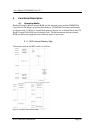
flash software should be executed. If the jumper is left open, the /EA pin is pulled up by a
10k pull-up resistor and the Flash MCU boots from internal flash memory. When the
MCU is reset with /EA at high level, the external memory can be accessed additionally.
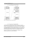
The entire ROM size would be 768 kb and 128 kb of ram. When the MCU is reset with
/EA at low level, the internal flash memory cannot be accessed additionally.
5.2. Jumper Description
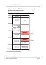
5.2.1. The jumpers of the Programming-Debugging Board
J_VCC : must only be opened when in-circuit debugging is performed with Flash Carrier
Board plugged in to a PGA socket of a target application with its own power supply. In all
other cases the jumper must be close to connect the power supply to the Flash Carrier
Board.
J_RES : Jumper to connect/disconnect the reset line controller by the firmware
controller. Should only be opened when in-circuit debugging is performed with a target
application with its own reset generation circuit.
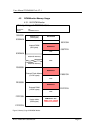
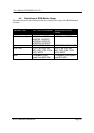
5.2.2. The jumpers of the Flash Carrier Board
J_CS0 : This jumper is to connect/disconnect the chip select line CS0 to the on-board
RAM device. If an external data/address bus is not required, it is recommended to open
this jumper. The CS0 pin can be used as a port pin additionally.
J_CS2 : Same as above. The CS2 pin is used to enable the on-board flash ROM device.
J_EA : Jumper to select between internal (high/open) and external flash memory access
(low/closed) after reset. When the Flash Carrier Board is connected to the Programming
and Debugging Board, the jumper can be left open – the line is controlled by the firmware
controller.
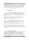
5.3. Programming of Flash Memory
Internal and external flash memories can be programmed with the respective tool. To start
it select the program group “TOPAS900 Flash” and select “TOPAS900 Flash
Programming Tool” from the menu. If there is no board connected a respective error
message will be displayed. If there is no physical connection this should be mounted. In a
lot of cases the reason is the COM port setting. You can set the COM and the transfer
data by clicking the “Setup Port” icon and use the setting options. If the connection is set