


Users Manual TOPAS900 Flash V2.1
HWU Elektronik Oberhausen Page 11
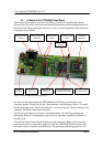
3.1.3. Status LEDs
There are two status LEDs on the board. A red one and a yellow one. The red Led is
controlled by the firmware processor and the yellow led is driven by the Flash MCU on
the Flash Carrier Board. The yellow Led can be used as a very simple output device to
show a internal state. Take a look at the LedDim sample to see how a Led can be dimmed
by pulse-width modulation.
3.1.4. Control Switches (Reset and NMI)
On the Programming and Debugging Board two switches (keys) are mounted. The Reset-
switch resets the firmware processor. After reset it lets boot the Flash MCU from external
flash memory. Normally the external memory contains one of the two ROM monitors
(IAR/Toshiba).
The second switch is to give a falling edge to the Flash MCU's NMI (non-maskable
interrupt) input. The Toshiba ROM monitor reacts with stopping the user software, if it
runs.
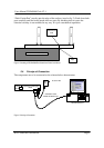
3.1.5. Serial Communication, Connector and Line Driver
The serial communication is build by a null-modem cable connected between the PC and
the TOPAS900 Flash Board. For connection the board has a 9-pin D-sub male connector.
To adapt the level between RS-232 and TTL a common RS-232 line driver is used. The
serial communication between PC and firmware controller uses the parameter 9600,8,N,1.
This baudrate is only used for control commands. The communication speed between
Windows-Software and MCU on the Flash Carrier Board is always 38400 baud.
The communication uses the TxD and RxD lines only. These two lines are directly wired
with the 10-pin connector to the Flash MCU. The firmware controller is connected in
parallel. Both, the firmware processor and the Flash MCU are connected to the RxD and
TxD line. To avoid both processors sending data to the same line the firmware processor
switches it TxD output to high impedance when it is not used by the firmware itself.
3.1.6. Connector to Flash Carrier Board
To connect the Flash Carrier Board a 10-pin connector is mounted at the edge of the
board. The 10-pin cable is to be plugged in on both sides to connect both boards together.
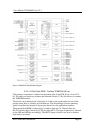
3.2. The Flash Carrier Board
The Flash Carrier Board is composed of the following parts:
• The TMP95FY64F Microcontroller
• 512 kb Flash ROM TC58F400 (90 ns)
• 128 kb RAM TC551001 (70 ns)
• Connector to Programming and Debugging Board
• MCU Terminal Connectors
• Jumpers