


Users Manual TOPAS900 Flash V2.1
HWU Elektronik Oberhausen Page 23
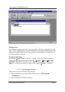
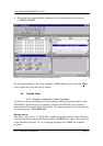
LOAD“ to load a program. The TMPro Debugger displays the source code in the source
window and automatically downloads the user program to the TOPAS900 Flash board.
After downloading a user program to the TOPAS900 Flash board RAM it can be started
(clicking go button) or traced (clicking one of the step buttons) by TMPro debugger. If a
user program is running the red LED on the TOPAS900 Flash board is switched on
permanently. Running programs can be stopped by TMPro debugger (click stop or finish
button), by a breakpoint being defined before (break set at a specific source code line) or
by actuating NMI switch on the TOPAS900 Flash board. The next statement of the user
program to execute is marked in the source code window.
For further details please refer to the help manual in the “Toshiba Debugger” program
group.
After starting the TMPro Debugger, a profile file which comprises a lot of settings for a
user program should be loaded or – if not existing – created.
If TMPro is called the first time after installing the creation of a new debugging profile is
necessary. From this profile further individual profiles can be derived. Before starting the
TMPro debugger be sure that the Toshiba ROM monitor is installed properly on the
TOPAS900 Flash board (external flash ROM) and is started (by pressing the reset
button). The yellow led must be flashing as an indicator for “Toshiba ROM monitor
running”.
4.2.2.1. How to create a new debugging profile (*.tdp)
The following steps show how to setup a new profile. Just follow the steps below, which
give a short description. Please refer to the TMPro help file for further information (topic:
Starting the Profile Wizard and Wizard Processing).
• Launch the TMPro Debugger by clicking its icon in the start menu.
• Select New Profile from the File menu
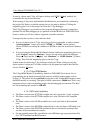
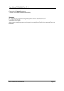
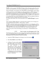
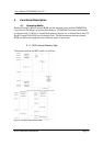
• A dialog will come up and requires
information about the connection.
Select the COM-port that is used for
the serial connection to the
TOPAS900 Flash Board. The DTE-
Speed must be set to 38400 baud as
shown on the left side. Confirm this
dialog for the next step. After
confirmation the serial connection to
the TOPAS900 Flash board’s ROM
monitor is established.