


Users Manual TOPAS900 Flash V2.1
HWU Elektronik Oberhausen Page 9
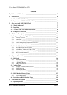
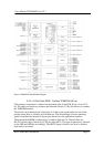
“Flash Carrier Part” exactly onto the edge of the surface (see also fig. 2). Push down both
parts carefully until the board breaks into two parts. By breaking into two parts the
electrical circuitry is not modified in any way. It is just a mechanical separation.
TOPAS900 Flash Board Flash Carrier
Edge
Scratch on the
PCB
Push
Push
Desk or other stable basis
Figure 2 : Breaking off TOPAS900 Flash Board from Flash Carrier Board
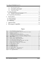
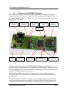
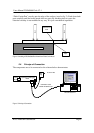
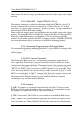
2.4. Principe of Connection
The components are to be connected as the scheme below demonstrates:
Windows-based PC
Null-Modem Cable
RS232 with 38400 baud
Net
Plug
AC Power Net
Programming & Debugging
Board
Flash
Carrier
Board
Figure 3 : Principe of Connection