


Users Manual TOPAS900 Flash V2.1
HWU Elektronik Oberhausen Page 32
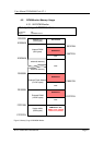
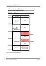
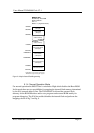
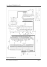
Internal RAM
(8K bytes)
Internal I/O
(160 bytes)
000000H
0000A0H
0020A0H
external memory
external memory
FFF800H
Internal Boot ROM
FFFFFFH
MEMORY MAP
Boot Memory : Boot ROM
Reset-Conditions :
/EA = H
/BOOT = L (single boot mode)
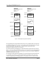
Internal Flash ROM
(256K bytes)
ROMSTART*
External Flash Memory
(512 K bytes)
* ROMSTART is programmed by CS2 registers
* RAMSTART is programmed by CS1 registers
External RAM
(128 K bytes)
RAMSTART*
010000H
04FFFFH
Figure 12 : Map for Internal Flash Programming
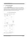
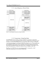
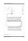
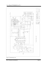
5.1.4. Normal Operation Mode
For normal operation the /BOOT line is switched to High which disables the Boot-ROM.
In this mode there are two possibilities for mapping the internal flash memory determined
by the /EA (external address) line. The TOPAS900 Flash board has external flash
memory for the ROM-Monitors and/or user programs and external RAM mainly for
program debugging. The /EA line enables/disables the internal flash and performs the
mappings shown in fig.7 and fig. 8.