27
Installation and
connection
CONTENTS
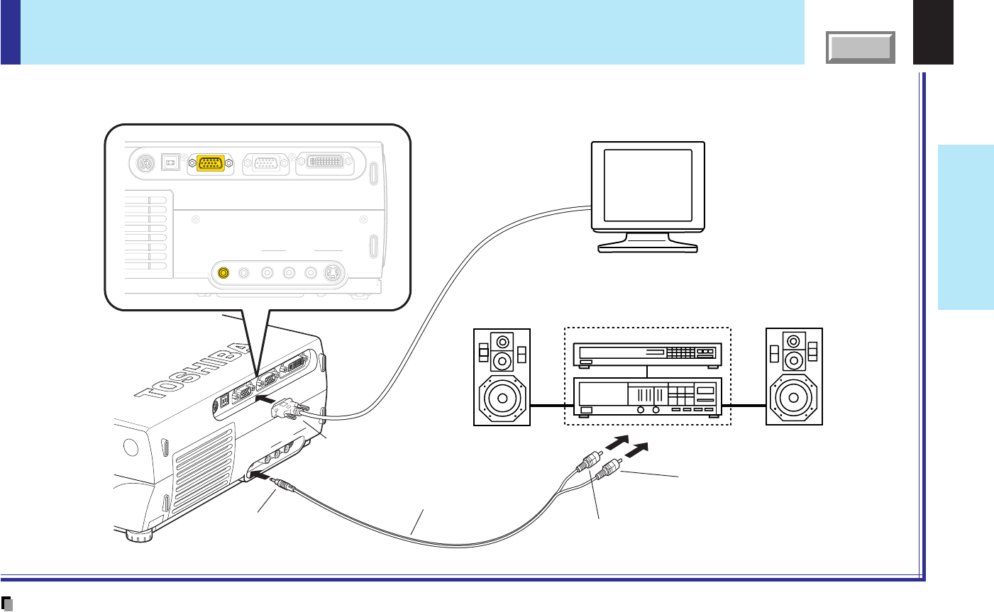
How to use the output connector
USB MONITOR OUT
COMPUTER IN 1
(
Y/P
B
/P
R
)
COMPUTER IN 2CONTROL
S-VIDEOVIDEO
VIDEO IN
R - AUDIO - L
AUDIO
IN
AUDIO
OUT
USB MONITOR OUT
COMPUTER IN 1
(
Y/P
B/PR
)
COMPUTER IN 2CONTROL
S-VIDEOVIDEO
VIDEO IN
R - AUDIO - L
AUDIO
IN
AUDIO
OUT
Pin plug (red)
To audio input (R)
To AUDIO OUT jack
To MONITOR OUT connector
Be sure to connect in the proper
direction.
Audio cable (not supplied)
Stereo system, etc.
Computer monitor, etc.
Pin plug (white)
To audio input (L)
You can output video and audio signals to a computer monitor, a stereo system, etc.
Check that the power for the projector and the equipments is off before connecting the cables.
Notes
• The audio signals of the input source selected by the input select operation are output from the AUDIO OUT jack. The signal level (volume) is fixed.
• The analog RGB signals of the COMPUTER IN 1 or COMPUTER IN 2 connector selected by the input select operation are output from the MONITOR
OUT connector. If neither of these input sources is selected, the analog RGB signal of the COMPUTER IN 1 connector is output. (Digital RGB signals
are not output.)
• Signals are output from the MONITOR OUT connector even when in the standby mode.
• Do not turn the projector on or off with the stereo system, etc., turned on. This may damage the stereo’s speakers.


