


2. Unit Description
2.1. The Master (Main) Unit
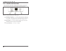
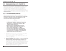
2.1.1. Master Unit Front Panel
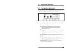
As shown in Figure 2.1, the front panel of the IPS-15 Master Unit
includes connectors, LEDs and a manual control button.
À
Link Port: An RJ-11 port, used to connect the IPS-15 Master
Unit to the optional Satellite Unit(s). For more information,
please refer to Section 4.5.
Á
Console Port: A DB9, RS232 serial port (DTE), for
connection to a local terminal or external modem, as
described in Section 4.3.
Â
Network Port: An RJ45 Ethernet Port for connection to your
TCP/IP network. The default IP Address is 192.168.168.168,
for more information, please refer to Section 5.3.1 and
Section 4.4.
Ã
ACT Indicator: Flashes to indicate activity at the Network
Port.
Ä
PWR Indicator: Lights when Power is Applied to the
Master Unit. Note that this LED does not indicate the On/Off
status of the Master Unit's switched AC outlet.
Å
RDY Indicator: Flashes when the IPS-15 Master Unit is
ready to receive commands.
Figure 2.1: IPS-15 Master Unit - Front Panel