Figures
x 975-0046-01-01
Figure 1-27 Ground Connections for an On-Grid Application with an AC Distribution
Panel (sub panel) and a Generator Disconnect Breaker in the ACCB - - - - 1–31
Figure 1-28 Neutral Connections for an On-grid Application with an AC Distribution
Panel and internal Generator Disconnect Breaker in the ACCB - - - - - - - - 1–32
Figure 1-29 Hot Connections for an On-Grid Application with an AC Distribution
Panel and an Internal Generator Disconnect - - - - - - - - - - - - - - - - - - - - - 1–33
Figure 1-30 Wiring an On-Grid Application Using Additional Circuit Breakers
in the ACCB Only - - - - - - - - - - - - - - - - - - - - - - - - - - - - - - - - - - - - - - 1–34
Figure 1-31 Ground Connections for an On-grid Application Using Additional Circuit
Breakers in the ACCB Only- - - - - - - - - - - - - - - - - - - - - - - - - - - - - - - - 1–35
Figure 1-32 Neutral Connections for an On-Grid Application Using Additional Circuit
Breakers in the ACCB Only- - - - - - - - - - - - - - - - - - - - - - - - - - - - - - - - 1–36
Figure 1-33 Hot Connections for an On-Grid Application Using Additional Circuit Breakers
in the ACCB Only - - - - - - - - - - - - - - - - - - - - - - - - - - - - - - - - - - - - - - 1–37
Figure 1-34 ISC-S Cable in an ISC-S/ICM Cable Slot of the ACCB - - - - - - - - - - - - - 1–39
Figure 1-35 Removing the Sems Screws From the ACCB Top Cover - - - - - - - - - - - - 1–40
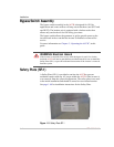
Figure 1-36 Installing the Safety Plate SP-1 on the ACCB- - - - - - - - - - - - - - - - - - - - 1–41
Figure 2-1 Bypass Switch Mode Summary - - - - - - - - - - - - - - - - - - - - - - - - - - - - - - 2–2
Figure 2-2 Normal Operation - - - - - - - - - - - - - - - - - - - - - - - - - - - - - - - - - - - - - - - 2–3
Figure 2-3 Bypass Operation- - - - - - - - - - - - - - - - - - - - - - - - - - - - - - - - - - - - - - - - 2–3
Figure 2-4 AC Output OFF - - - - - - - - - - - - - - - - - - - - - - - - - - - - - - - - - - - - - - - - - 2–4


