


User Interface Features
975-0052-01-01 Rev A 33
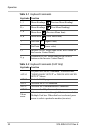
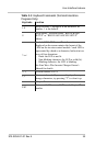
Table 3-3
Keyboard Commands (Terminal Emulation
Programs Only)
Keystroke Function
1-8
Select inverter: 1 through 8 is the inverter’s ID
number, 1 is the default.
S
Setup Menu - Accesses either “BEGIN BASIC
SETUP” or “BEGIN ADVANCED SETUP”
Menus.
? or /
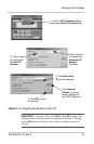
Sends ASCII LED Status. The information
displayed on the screen mimics the layout of the
LEDs on the inverter control module : each LED is
represented by a dash or a character, laid out in two
rows of four characters.
• Dash: the LED is not lit.
• Non-blinking character: the LED is solid (lit).
• Blinking character: the LED is blinking.
See Sine Wave Plus Inverter/Charger Owner's
Manual for details.
V, v Version number of ICA
T, t
Set terminal mode. If you see a display of many
strange characters, try pressing “T” to clear it up.
~ Adapter Reset
ESC
Retransmit LCD screen, LED’s, and Adapter ID
number