


Current Sharing
5–4 TM-XDOP-01XN
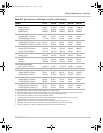
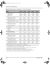
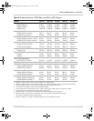
STAT:OPER:CSH:COND?
See Table 4-14, “Current SHare Sub-Register” on page 4–50 for a description of
the bits in this register.
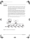
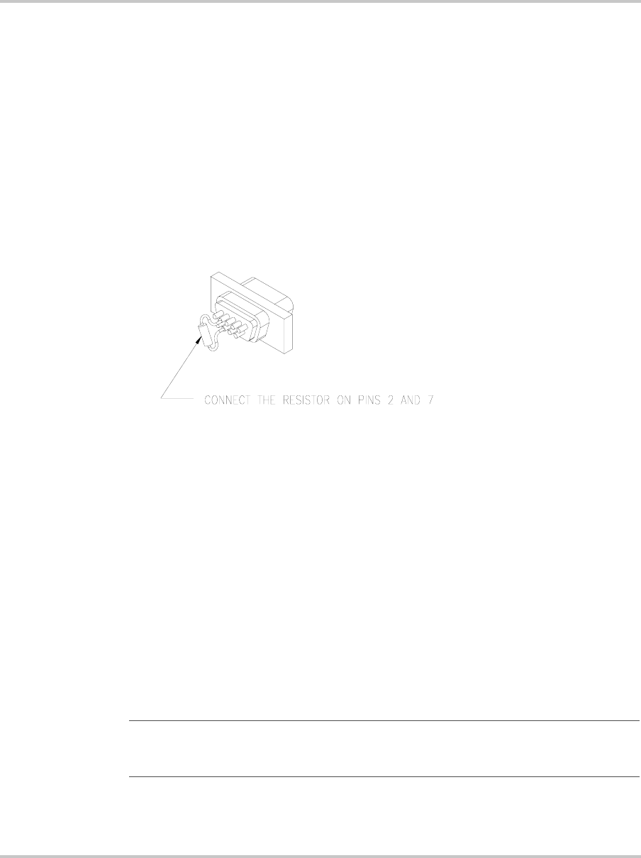
3. Connect the CANbus ports of all paralleled units and install terminators. See
figure below.
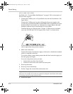
Connect the CANbus ports in series, linking the first power supply to the
second using a parallel male DB9 to female DB9 cable, and then the second to
the third using a second cable, etc. Alternatively a single ribbon cable with
multiple connectors may be used instead of several cables.
Terminate the bus at each end with a 120 ohm, 1/4 Watt resistor (included)
across the CAN HI and CAN LO signals (Pins 2 and 7) as shown below.
4. Make load connections.
Connect the output of each power supply to the load or a distribution terminal
which is connected to the load.
To provide reliable current sharing ensure that the lines from each supply are
the same gauge and length.
If you are using remote sense you must:
• Connect the sense lines from all units
• Connect all sense lines to the same load sense point.
5. Power up the master.
6. Power up slaves individually.
7. Set the voltage and current limit on the master unit.
8. Enable the output.
Female connector shown. Pinouts are reversed
(left to right) when using a male connector
Important:
Setting the current limit of the master results in the same current limit for
each slave. For example, if five units are connected, setting the current limit of the master
to 10 A may result in a system current of 50 A.
TM-XDOP-01XN.book Page 4 Monday, July 17, 2006 11:19 AM