50 MicroBlaze Development Kit Spartan-3E 1600 Edition User Guide
www.xilinx.com UG257 (v1.1) December 5, 2007
Chapter 5: Character LCD Screen
R
After the write operation, the address is automatically incremented or decremented by 1
according to the Entry Mode Set command. The entry mode also determines display shift.
Execution Time: 40 Ps
Read Data from CG RAM or DD RAM
Read data from DD RAM if the command follows a previous Set DD RAM Address
command, or read data from CG RAM if the command follows a previous Set CG RAM
Address command.
After the read operation, the address is automatically incremented or decremented by 1
according to the Entry Mode Set command. However, a display shift is not executed
during read operations.
Execution Time: 40 Ps
Operation
Four-Bit Data Interface
The board uses a 4-bit data interface to the character LCD.
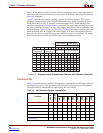
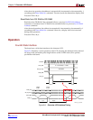
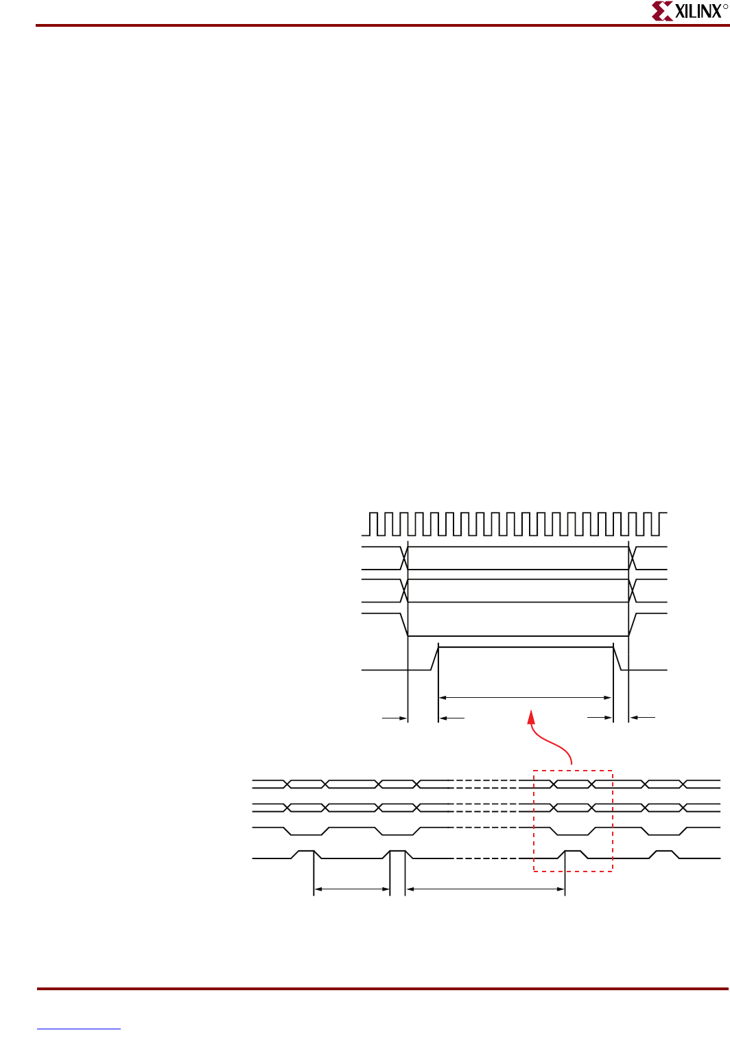
Figure 5-6 illustrates a write operation to the LCD, showing the minimum times allowed
for setup, hold, and enable pulse length relative to the 50 MHz clock (20 ns period)
provided on the board.
Figure 5-6: Character LCD Interface Timing
Upper
4 bits
Lower
4 bits
1 µs 40 µs
40 ns 10 ns
230 ns
Valid Data
CLOCK
LCD_RS
SF_D[11:8]
LCD_RW
LCD_E
LCD_RS
SF_D[11:8]
LCD_RW
LCD_E
0 = Command, 1 = Data
UG257_05_06_061406


