64 MicroBlaze Development Kit Spartan-3E 1600 Edition User Guide
www.xilinx.com UG257 (v1.1) December 5, 2007
Chapter 8: PS/2 Mouse/Keyboard Port
R
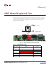
Both a PC mouse and keyboard use the two-wire PS/2 serial bus to communicate with a
host device, the Spartan-3E FPGA in this case. The PS/2 bus includes both clock and data.
Both a mouse and keyboard drive the bus with identical signal timings and both use 11-bit
words that include a start, stop and odd parity bit. However, the data packets are
organized differently for a mouse and keyboard. Furthermore, the keyboard interface
allows bidirectional data transfers so the host device can illuminate state LEDs on the
keyboard.
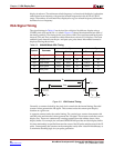
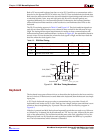
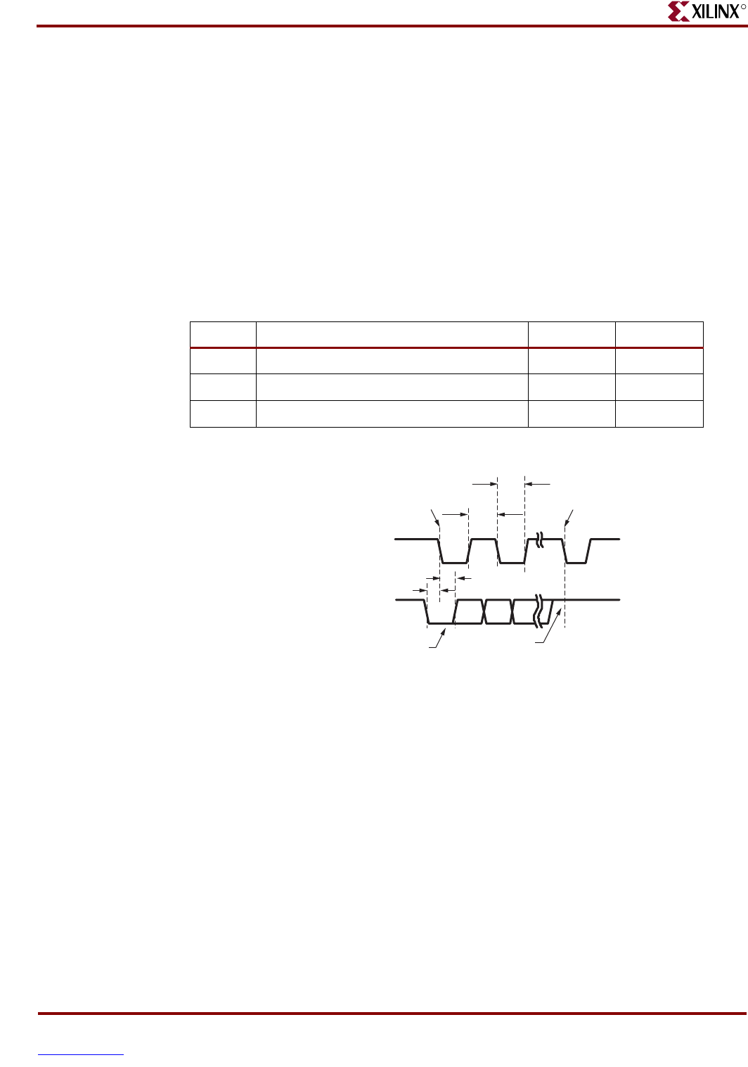
The PS/2 bus timing appears in Table 8-2 and Figure 8-2. The clock and data signals are
only driven when data transfers occur; otherwise they are held in the idle state at logic
High. The timing defines signal requirements for mouse-to-host communications and
bidirectional keyboard communications. As shown in Figure 8-2, the attached keyboard or
mouse writes a bit on the data line when the clock signal is High, and the host reads the
data line when the clock signal is Low.
Keyboard
The keyboard uses open-collector drivers so that either the keyboard or the host can drive
the two-wire bus. If the host never sends data to the keyboard, then the host can use simple
input pins.
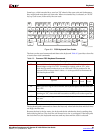
A PS/2-style keyboard uses scan codes to communicate key press data. Nearly all
keyboards in use today are PS/2 style. Each key has a single, unique scan code that is sent
whenever the corresponding key is pressed. The scan codes for most keys appear in
Figure 8-3.
If the key is pressed and held, the keyboard repeatedly sends the scan code every 100 ms or
so. When a key is released, the keyboard sends an “F0” key-up code, followed by the scan
code of the released key. The keyboard sends the same scan code, regardless if a key has
different shift and non-shift characters and regardless whether the Shift key is pressed or
not. The host determines which character is intended.
Table 8- 2: PS/2 Bus Timing
Symbol Parameter Min Max
T
CK
Clock High or Low Time 30 Ps 50 Ps
T
SU
Data-to-clock Setup Time 5 Ps 25 Ps
T
HLD
Clock-to-data Hold Time 5 Ps 25 Ps
Figure 8-2: PS/2 Bus Timing Waveforms
T
CK
T
SU
T
HLD
T
CK
Edge 0
Edge 10
CLK (PS2C)
DATA (PS2D)
0 start bit
1 stop bit
UG257_08_02_060506


