5
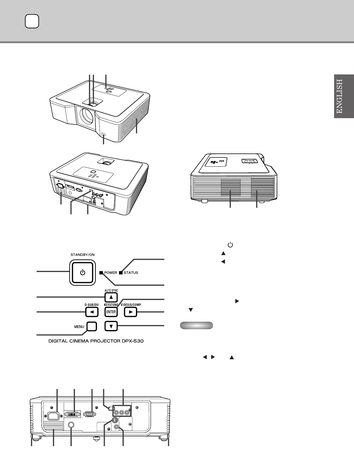
◆ Projector overview
1. FOCUS ring
2. ZOOM ring
3. Control panel
4. Air intake vent
5. Remote control sensor (Front)
6. Air exhaust vent
7. Air intake vent
8. Terminal board
9. Remote control sensor (Rear)
10. Air exhaust vent
Control area
1. STANDBY / ON, button
2. AUTO SYNC, button
3. D-SUB / DVI, button
4. MENU button
5. STATUS indicator
6. POWER indicator
7. KEYSTONE, ENTER button
8. VIDEO / S / COMP., button
9. button
Important
• While the menu is on the screen, the KEYSTONE button
functions as the ENTER button and the D-SUB / DVI,
VIDEO / S / COMP., and AUTO SYNC buttons function as
the , , and buttons respectively.
Rear panel
1. AC IN
2. DVI input terminal (DVI-D 24-pin with HDCP)
3. D-SUB input terminal
4. Remote control sensor (Rear)
5. COMPONENT input terminals
6. Foot adjustment buttons (Left/Right)
7. Air exhaust vent
8. SERIAL terminal (8-pin)
• Used for adjustment by service person.
9. S-VIDEO input terminal
10. VIDEO input terminal
321
5
4
8
10
9
7
6
2
1
3
4
8
5
6
7
9
AC IN
DVI
D-SUB
SERIAL
S-VIDEO
VIDEO
COMPONENT
YP
B/CB PR/CR
23145
8766910
Controls and functions2


