4-8
CHAPTER 4 Adjustment
3-1-2-2 Sensor method (X-axis, Y-axis)
WARNING
Serious injury might occur from physical contact with the robot during opera-
tion.
Never enter within the robot movement range during absolute reset.
!
CAUTION
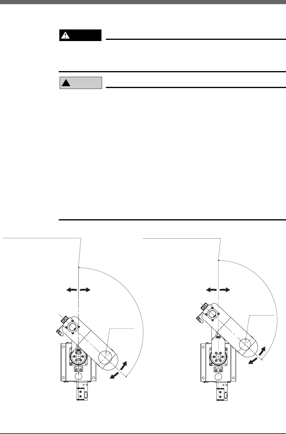
The origin cannot be detected in any axis which is not positioned on the plus
side from the origin (See Fig. 4-5.) before starting the return-to-origin opera-
tion. (Factory setting at shipment.)
In this case, press the STOP key to interrupt the return-to-origin operation,
move the target axis to the plus side of the origin, and reperform the origin
return operation.
If the return-to-origin operation is not stopped, the robot will continue moving
and could collide with the peripheral devices.
The X and Y-axes will move to the positions shown in Fig. 4-5 during return-to-
origin, so make sure that the tool on the end, the robot and the peripheral
devices do not interfere. The maximum tolerable load radius (when load is cy-
lindrical object) is shown in Fig. 4-5. If return-to-origin is performed with a load
larger than this radius installed on the R-axis, the base and load could interfere.
Since the X-axis arm first returns to the origin, the tool on the end might interfere
with the robot base (pedestal) if the Y-axis arm is near its origin.
X-axis origin is at 0°±5° with
respect to front of robot base
X-axis origin is at 0°±5° with
respect to front of robot base
133°±5°
133°±5
°
*1 When load is cylindrical object
YK180X
YK220X
R19
R17
Plus side Minus side Plus side Minus side
Minus side
Plus side
Minus side
Plus side
Maximum
tolerable
load radius
*1
Maximum
tolerable
load radius
*1
Fig. 4-5 Default origin position


