


Chapter 7 Basic Setting
GS-3012/GS-3012F User’s Guide
73
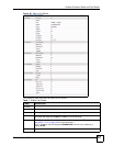
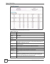
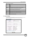
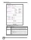
7.3 General Setup
Click Basic Setting and General Setup in the navigation panel to display the screen as shown.
Use this screen to configure general settings such as the system name and time.
Figure 31 General Setup
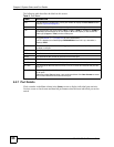
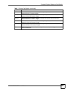
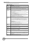
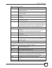
MAX This field displays this fan's maximum speed measured in Revolutions Per Minute
(RPM).
MIN This field displays this fan's minimum speed measured in Revolutions Per Minute
(RPM).
Threshold This field displays the minimum speed at which a normal fan should work.
Status Normal indicates that this fan is functioning above the minimum speed. Error
indicates that this fan is functioning below the minimum speed.
Voltage (V) The power supply for each voltage has a sensor that is capable of detecting and
reporting if the voltage falls out of the tolerance range.
Current This is the current voltage reading.
MAX This field displays the maximum voltage measured at this point.
MIN This field displays the minimum voltage measured at this point.
Threshold This field displays the minimum voltage at which the switch should work.
Status Normal indicates that the voltage is within an acceptable operating range at this
point; otherwise Error is displayed.
Table 8 System Info (continued)
LABEL DESCRIPTION