


11
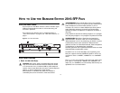
4 Module Active LEDs
The Module Active LEDs shows the status of any SFP modules
that are installed.
5 Port Duplex LEDs
The second and fourth (bottom) row of Status LEDs, which are
colored yellow, show the duplex status of the related ports.
6 Power LED
The Power LED shows the power status of the Switch:
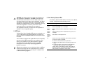
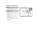
7 Self-adhesive Pads
The unit is supplied with four self-adhesive rubber pads.
Do not apply the pads if you intend to rack mount the unit.
If the unit is to be part of a free-standing stack, apply the pads
to each marked corner area on the underside of the unit. Place
the unit on top of the lower unit, ensuring that the pads locate
with the recesses of the lower unit.
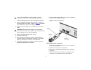
Rear Panel Features
8 Power Supply
The Switch automatically adjusts to the supply voltage. Only use
the power cord that is supplied with the unit.
9 Recovery button
The recovery button reinitializes the Switch. This returns the
Switch to the factory default settings if, for example, you have
forgotten the default IP address, or forgotten your user name or
password.
Status Meaning
Green Fiber SFP is inserted in the slot.
Off No fiber SFP is inserted in the slot.
Status Meaning
Off No link, not yet negotiated or the port is operating in
half-duplex mode.
Yellow The port is operating in full-duplex mode.
Status Meaning
Green The unit is powered on and ready for use.
Off ■ The unit is not receiving power:
■ Check that the power cord is connected correctly.
■ If the unit still does not operate, contact your supplier.
Status Meaning
Flashing
Green
■ Power-on self test is in progress.
Yellow ■ Power-on self test or loopback test failed. Switch is in fail-
safe mode.