27
Uplink VLAN Configuration Example
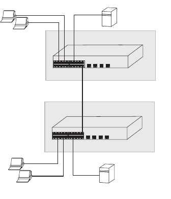
Figure 13 Uplink VLAN Configuration Example
This example explains how you can set up a VLAN Configuration
across two Switches using Uplink connections. This enables ports
that are members of the same VLAN, but which are on different
switches to communicate, provided that a port on each switch is
set to Uplink, and that these ports are connected.
To set up the configuration shown in Figure 13, do the following:
1 Use the Create VLANs screen (Figure 14) to create VLAN2 on
both Switch 1 and Switch 2, and assign the same name to it.
(VLAN1 is the default VLAN and already exists.)
2 In the Modify VLANs screen (Figure 16) for Switch 1, select
Desktop from the Mode drop down list for the ports you want to
add to VLAN2.
3 Select 2 from the VLAN ID drop down list for the ports you want
to add to VLAN2.
4 Repeat steps 2 and 3 for Switch 2.
5 Select Uplink as the Mode for port 16 on Switch 1.
6 Select Uplink as the Mode for port 8 on Switch 2.
7 Connect port 16 on Switch 1 to port 8 on Switch 2.
Those ports on Switch 1 that are members of VLAN2 can now
communicate with those ports on Switch 2 that are members of
VLAN2.
Switch 1 Port 16 in VLANs 1 and 2 (Uplink)
Endstation
in VLAN 2
(Desktop)
n
stat
on
in VLAN 1 (Desktop)
Server
in VLAN 1 (Desktop)
Endstation
in VLAN 2
(Desktop)
Endstation
in VLAN 1
Deskto
Server
in VLAN 2 (Desktop)
Switch 2 Port 8 in VLANs 1 and 2 (Uplink)


