


10
C
ORE
B
UILDER
®
5000 S
WITCH
M
ODULE
Q
UICK
S
TART
AND
R
EFERENCE
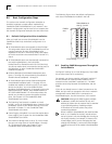
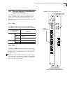
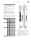
11.1 LEDs
The following table explains the 10BASE-T port status or
activity LED blink sequences:
Port Status or Activity
LED State
Indicates
Green On Port is enabled and link is OK.
Blinking Link failure or waiting for network
connection.
Off Port or port functions are disabled.
Yellow On Heavy traffic activity on the port.
Blinking Normal traffic activity on the port.
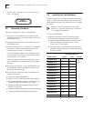
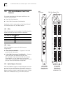
11.2 Ports
10BASE-T SwitchModules use the following port types:
■ The 12-Port, 20-Port, and 24-Port 10BASE-T
SwitchModules use crossover ports with
RJ-45 connectors.
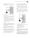
CoreBuilder 5000 10BASE-T modules use crossover
ports. This means that if you connect a 10BASE-T
SwitchModule port to another CoreBuilder 5000
10BASE-T module port, you must use a crossover
cable.
■ The Ethernet Telco SwitchModule uses two standard
female Telco connectors with 12 ports per connector for a
total of 24 ports.
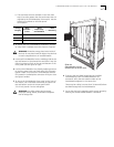
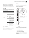
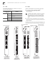
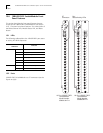
The following illustrations show these SwitchModules. The
X that follows the port numbers indicates a crossover port.
Port Status/Activity
LEDs
24-Port 10BASE-T
SwitchModule
Model Number
3C96624M-TP-A
6624M-TP-A
4X
1X
3
4
2X
3X
5
6
7
8
1
2
9
10
11
12
5X
6X
7X
8X
9X
10X
11X
12X
1
6
X
1
3
X
1
5
1
6
1
4
X
1
5
X
1
7
1
8
1
9
2
0
1
3
1
4
2
1
2
2
2
3
2
4
1
7
X
1
8
X
1
9
X
2
0
X
2
1X
2
2
X
2
3
X
2
4
X
Port Status/Activity
LEDs
24-Port Ethernet
Telco SwitchModule
Model Number
3C96624M-TPL-A
6624M-TPL-A
1X-12X
4
6
8
2
10
12
16
18
20
14
22
24
3
5
7
1
9
11
15
17
19
13
21
23
13X-24X
Standard female
Telco connectors
12-Port 10BASE-T
SwitchModule
Model Number
3C96612M-TP-A
6612M-TP-A
4X
1X
3
4
2X
3X
5
6
7
8
1
2
9
10
11
12
5X
6X
7X
8X
9X
10X
11X
12X
4X
1X
3
4
2X
3X
5
6
7
8
1
2
9
10
11
12
5X
6X
7X
8X
9X
10X
11X
12X
RJ-45 connectors
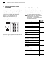
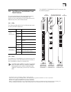
20-Port
10BASE-T
SwitchModule
Model Number
3C96620M-TP-A
P
A
C
K
E
T
C
H
A
N
N
E
L
M
O
D
S
T
A
T
R
E
S
E
T
10
13
16
1
9
1
4
7
1
X
2
X
3X
4
X
5
X
6
X
7X
8X
9
X
10
X
1
1X
12
X
1
3
X
1
4
X
1
5
X
16
X
1
7
X
18
X
1
9
X
20
X
6620M-TP-A