


6
C
ORE
B
UILDER
®
5000 S
WITCH
M
ODULE
Q
UICK
S
TART
AND
R
EFERENCE
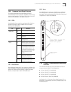
8.0 Basic Configuration Steps
This section uses network configuration examples to
introduce important concepts about implementing
CoreBuilder 5000 SwitchModules in your network. Your
network configuration may be more or less complex than
the network configuration examples that are shown here.
8.1 Default Configuration After Installation
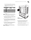
After you install one or more SwitchModule into the
CoreBuilder 5000 hub, the default configuration is as
follows:
■ All SwitchModule ports are assigned to virtual bridge 1.
This assignment means that all SwitchModule ports can
communicate with all other SwitchModule ports,
regardless of the slot in which they reside, and subject
to the slot restrictions that are described in Section 3.2,
step 4.
■ All SwitchModule ports are automatically connected to
the switching backplane in the hub (either
PacketChannel or PacketChannel with Cell-Switching).
You do not need to enter a command to assign ports to
the backplane, as other CoreBuilder 5000 media
modules may require.
■ Ethernet Backplane SwitchModule backplane ports
(ports 17 through 24) are permanently connected to
shared Ethernet backplanes 1 through 8.
■ All SwitchModule ports (except Ethernet Backplane
SwitchModule backplane ports 17 through 24) are
enabled and capable of switching traffic if you attach
devices to the ports. You must enable Ethernet
Backplane SwitchModule ports 17 through 24 using the
DMM command SET BPORT_MAU MODE ENABLE or
SET PORT MODE ENABLE. For information about the
special port numbering system that applies to these
ports, see Chapter 4 in the
CoreBuilder 5000
SwitchModule User Guide
.
■ The Spanning Tree Protocol is enabled on virtual
bridge 1 and on all SwitchModule ports. Spanning Tree
parameters are set to their default settings, which are
described in Chapter 7 in the
CoreBuilder 5000
SwitchModule User Guide
.
■ Frame Tagging is disabled. For more information about
frame tagging, see Chapter 8 in the
CoreBuilder 5000
SwitchModule User Guide
.
■ The maximum vbridge value is set to 32, which means
that you can assign ports to virtual bridges 1 through
32. To change this value, see Chapter 2 in the
CoreBuilder 5000 SwitchModule User Guide
.
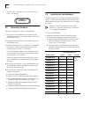
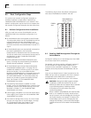
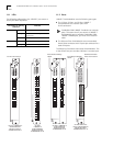
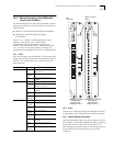
The following figure shows the default configuration
with three SwitchModules installed in the hub:
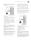
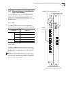
8.2 Enabling SNMP Management Through the
SwitchModule
Configure IP settings for a virtual bridge only if the DMM
has no other means of IP connectivity.
For example, you do not need to configure IP settings if
the hub contains an Ethernet media module with a
network monitor card (NMC) attached to it. The NMC
provides connectivity between SwitchModules and the
DMM.
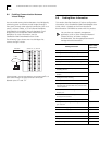
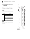
If you do not already have an in-band connection to the
DMM, and you want to manage the hub from a network
management station (NMS) that is connected to a
SwitchModule port, use the instructions in this section.
CAUTION:
Although the DMM supports multiple
IP addresses, enable the interface for only one
address per subnet (on the network that is attached
to your default gateway). Enabling multiple
IP interfaces on the same subnet may cause
connectivity problems.
When a model A SwitchModule (the model number
ends in -A) is installed in the hub, include at least
one of its ports in the virtual bridge that is acting as
the IP relay interface. For example, if there are five
virtual bridges, and if you are managing the hub
through virtual bridge 1, ensure that virtual bridge 1
includes at least one of the model A SwitchModule’s
ports.
Virtual bridge 1
SwitchModules in
slots 2, 3, and 4
DMM in
slot 1