


C
ORE
B
UILDER
®
5000 S
WITCH
M
ODULE
Q
UICK
S
TART
AND
R
EFERENCE
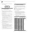
5
c
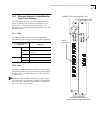
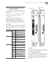
The total watts that are available in the hub (from
step a) must be greater than the total watts that are
required by the SwitchModules (from step b). Use the
following worksheet to calculate power
consumption:
2
To expose slots for SwitchModule installation, remove
as many blank faceplates from the chassis as required.
WARNING:
Hazardous energy levels exist inside of
the hub. Do not place hands or objects into the hub
or touch components on an inserted module.
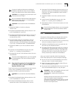
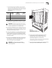
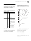
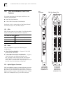
3
Insert each SwitchModule into the module guides at the
top and bottom of the selected slot and slide it into the
chassis by pressing firmly at the top and bottom of the
front panel (see the figure at right).
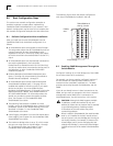
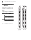
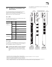
4
Lock the SwitchModules into place by applying pressure
to the front panel with one hand while you close each
ejector handle. Ensure that the SwitchModule remains
fully seated in the backplane connector while you close
the ejector handles.
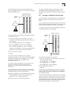
5
To secure the SwitchModule front panel to the front of
the chassis, use a flat-blade screwdriver to tighten the
top and bottom screws to torque specification
3 to 5 inch pounds. Do not overtighten.
WARNING:
For safety reasons and to ensure
adequate cooling airflow, install blank faceplates
over all empty slots.
Voltage
Category
Watts
Available
in Hub
–
Watts
Required by
SwitchModule
=
Watts
Remaining
+5
–
=
–5
–
=
+12
–
=
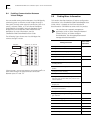
6
To ensure that the DMM recognizes the installed
SwitchModule, enter the SHOW MODULE ALL
command. Verify that the model number of the
SwitchModule appears in the correct slot.
There may be a delay (no more than 30 seconds) before
the DMM recognizes the SwitchModule.
7
Ensure that the hub is operating with enough power by
entering the SHOW POWER BUDGET command.
Slide the
SwitchModule into the
selected slot as shown here.