


12
C
ORE
B
UILDER
®
5000 S
WITCH
M
ODULE
Q
UICK
S
TART
AND
R
EFERENCE
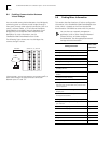
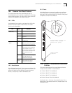
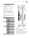
13.0 10BASE-FB/FL SwitchModule Front
Panel Features
This section describes the front panel features that are
unique to the 10BASE-FB/FL SwitchModule. See Section
10.0, "Common Front Panel Features" for a description of
the PacketChannel LED, Module Status LED, and Reset
button.
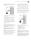
13.1 LEDs
The following table explains the 10BASE-FB/FL port status
or activity LED blink sequences:
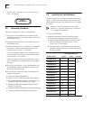
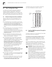
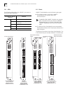
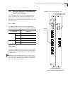
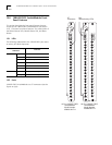
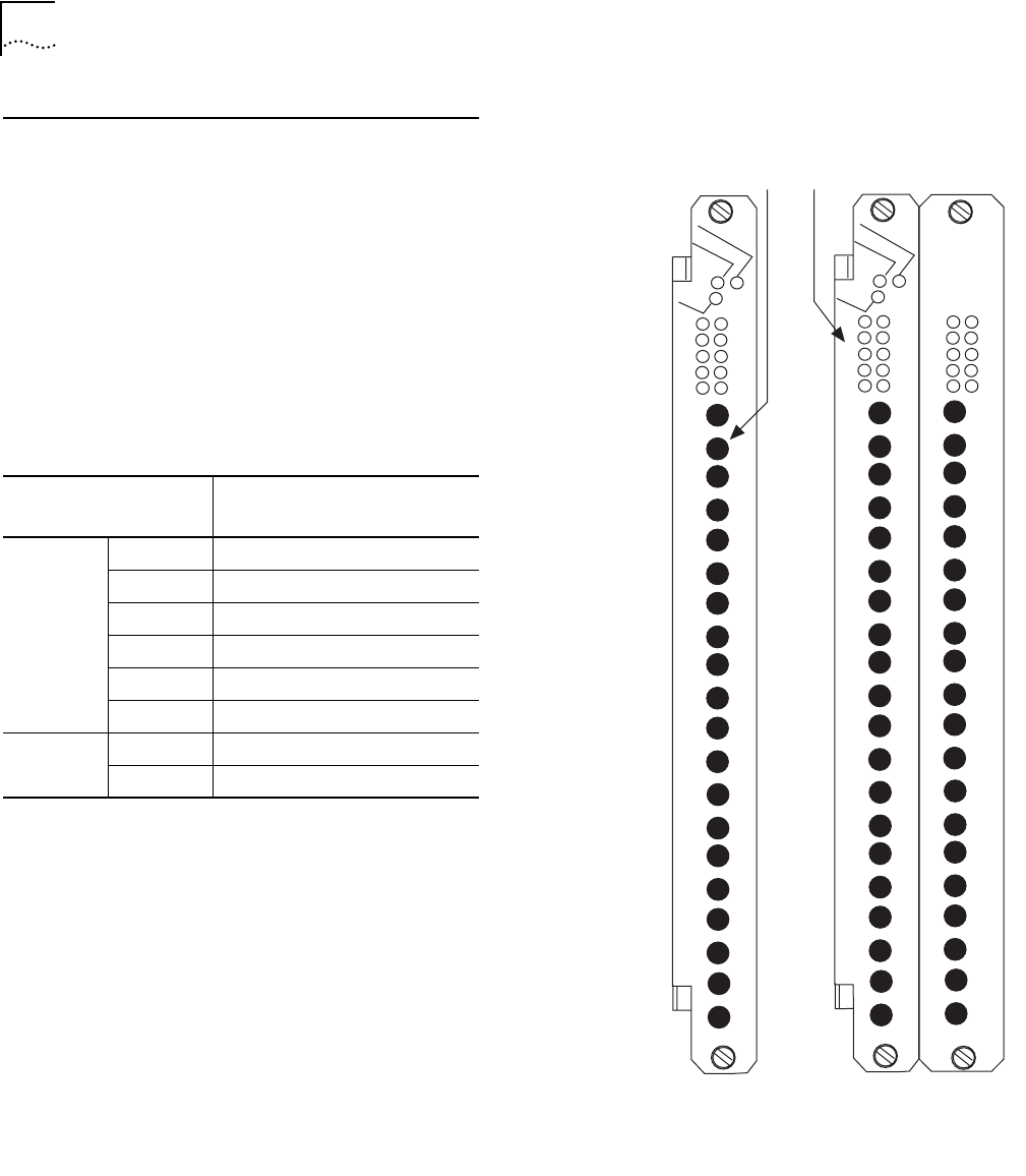
13.2 Ports
10BASE-FB/FL SwitchModules use ST connectors (see the
figures at right).
Port Status or Activity
LED State
Indicates
Green On Port is enabled and link is OK.
1 Blink No light on receive fiber.
2 Blinks Port received jabber.
3 Blinks Port is partitioned.
4 Blinks Remote fault.
Off Port or port functions are disabled.
Yellow On Heavy traffic activity on the port.
Blinking Normal traffic activity on the port.
6620M-F-A
Port
Status/Activity LEDs
20-Port 10BASE-FB/FL
SwitchModule
Model Number
3C96620M-F-A
6610M-F-A
10-Port 10BASE-FB/FL
SwitchModule
Model Number
3C96610M-F-A
ST
connectors
1
2
3
4
5
6
7
8
9
10
RX
TX
RX
TX
RX
TX
RX
TX
RX
TX
RX
TX
RX
TX
RX
TX
RX
TX
RX
TX
2
1
6
8
5
7
10
9
4
3
1
2
3
4
5
6
7
8
9
10
RX
TX
RX
TX
RX
TX
RX
TX
RX
TX
RX
TX
RX
TX
RX
TX
RX
TX
RX
TX
2
1
6
8
5
7
10
9
4
3
12
11
16
18
15
17
20
19
14
13
11
12
13
14
15
16
17
18
19
20
RX
TX
RX
TX
RX
TX
RX
TX
RX
TX
RX
TX
RX
TX
RX
TX
RX
TX
RX
TX