


4
C
ORE
B
UILDER
®
5000 S
WITCH
M
ODULE
Q
UICK
S
TART
AND
R
EFERENCE
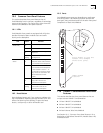
IEC 825, Class 1 LED Device. For connection only to
Class 1 LED Devices.
6.0 Unpacking Procedure
Follow this procedure to unpack a SwitchModule:
1
Verify that the SwitchModule is the model that you
ordered by examining the model number on the side of
the shipping carton.
2
Remove the SwitchModule, in its antistatic bag, from
the shipping carton.
3
Following the instructions in Section 5.0, "Installation
Precautions", remove the SwitchModule from the
antistatic bag and inspect it for damage.
If the SwitchModule appears to be damaged, return it
to the antistatic bag, repack it in the shipping carton,
and contact your local supplier.
Keep the shipping carton and antistatic bag in which
your SwitchModule was shipped for future storage or
shipment.
4
Record the serial number of your SwitchModule. Use
the
CoreBuilder 5000 SwitchModule Planning Chart
that comes with this product.
5
Ensure that the CoreBuilder 5000 SwitchModule Kit
contains these items:
■
CoreBuilder 5000 SwitchModule
■
Release Note for CoreBuilder 5000 SwitchModules
■
3Com
DocsOnCD
documentation CD-ROM (contains
CoreBuilder 5000 SwitchModule User Guide
)
■
CoreBuilder 5000 SwitchModule Quick Start and
Reference
(this guide)
■
CoreBuilder 5000 SwitchModule Command Reference
■
CoreBuilder 5000 SwitchModule Planning Chart
CLASS 1
LED PRODUCT
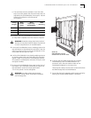
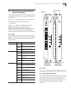
7.0 Installing the SwitchModule
You do not need to turn off the CoreBuilder 5000 hub to
install
or
remove
the SwitchModule. You can install the
SwitchModule while the hub is operating (which is called a
hot swap
).
Before you start the installation process, read
Section 3.3, "Software Prerequisites," and Section
5.0, "Installation Precautions".
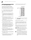
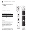
To install a SwitchModule:
1
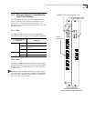
Determine hub power. To ensure that the hub has
enough power to support the new SwitchModule:
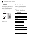
a
Enter the SHOW POWER BUDGET command to see if
sufficient wattage is available from the +5 volt,
–5 volt, and +12 volt supplies.
b
Using the values in the following table, add up the
total power requirements for the SwitchModules that
you plan to install:
Power Requirement at
Model Number +5 Volts –5 Volts +12 Volts
3C96618M-TX-A
52 W 0.5 W 0.25 Watts
for all
modules
3c96620M-TP-A
25 W 0.5 W
3C96612M-TP-A
23 W 0.5 W
3C96624M-TP-A
30 W 0.5 W
3C96624M-TPL-A
25 W 0.5 W
3C96616M-BTP-A
35 W 1.0 W
3C96610M-F-A
33 W 0.5 W
3C96620M-F-A
50 W 0.5 W
3C96614M-FTP-A
30 W 0.5 W
3C96612M-FF-A
40 W 0.5 W
3C96604M-F-A
31 W 0.5 W
3C96612M-FC-A
57 W 0.5 W
3C96604M-TX-A
34 W 0.5 W
3C96604M-FX-A
35 W 0.5 W