


C
ORE
B
UILDER
®
5000 S
WITCH
M
ODULE
Q
UICK
S
TART
AND
R
EFERENCE
11
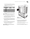
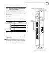
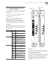
12.0 Ethernet Backplane SwitchModule
Front Panel Features
This section describes the front panel features that are
unique to the Ethernet Backplane SwitchModule. See
Section 10.0, "Common Front Panel Features" for a
description of the PacketChannel LED, Module Status LED,
and Reset button.
12.1 LEDs
The following table explains the Ethernet Backplane
SwitchModule port status or activity LED blink sequences:
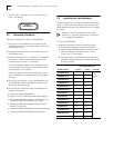
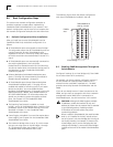
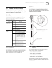
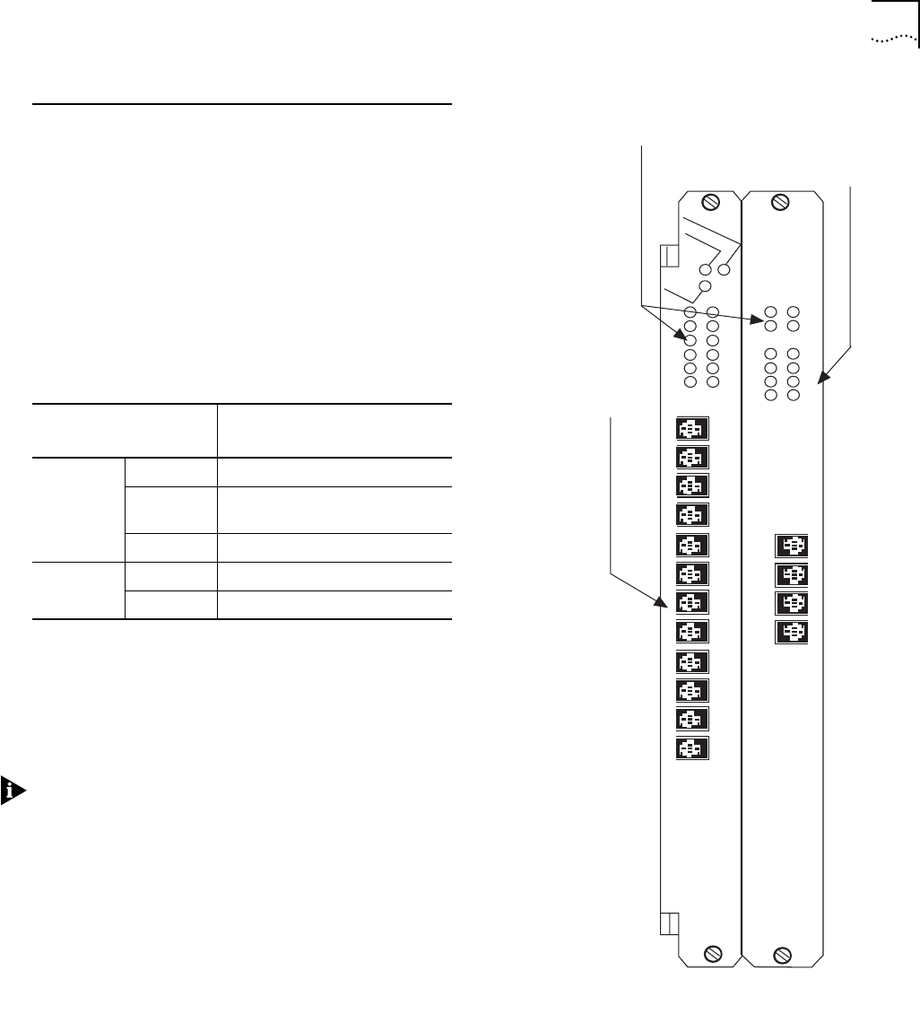
12.2 Ports
The Ethernet Backplane SwitchModule front panel ports
use crossover ports with RJ-45 connectors (see the figure
at right). The X that follows the port number indicates a
crossover port.
CoreBuilder 5000 10BASE-T modules use crossover ports.
This means that if you connect a 10BASE-T SwitchModule
port to another CoreBuilder 5000 10BASE-T module port,
you must use a crossover cable
Port Status or Activity
LED State
Indicates
Green On Port is enabled and link is OK.
Blinking Link failure or waiting for network
connection.
Off Port or port functions are disabled.
Yellow On Heavy traffic activity on the port.
Blinking Normal traffic activity on the port.
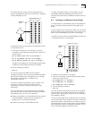
6616M-BTP-A
4X
1X
3
4
2X
3X
5
6
7
8
1
2
9
10
11
12
5X
6X
7X
8X
9X
10X
11X
12X
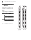
10BASE-T Port Status/Activity LEDs
15
16
17
18
19
20
13
14
21
22
23
24
Ethernet Backplane Port
Status/Activity LEDs
16X
13X
14X
15X
16-Port Ethernet
Backplane SwitchModule
Model Number 3C96616M-BTP-A
RJ-45
connectors