


14
C
ORE
B
UILDER
®
5000 S
WITCH
M
ODULE
Q
UICK
S
TART
AND
R
EFERENCE
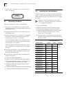
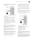
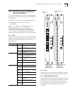
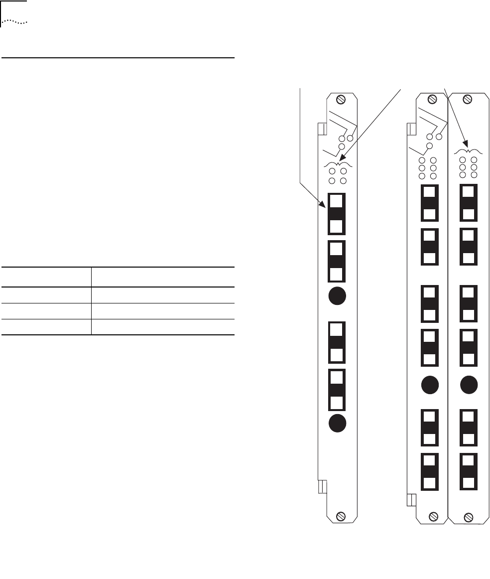
15.0 FDDI SwitchModules Front Panel
Features
This section describes the FDDI ports and LEDs on the
following SwitchModules:
■ 2-Port FDDI SwitchModule
■ 12-Port FDDI Concentrator SwitchModule
See Section 10.0 for a description of the PacketChannel
LED, Module Status LED, and Reset button.
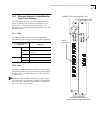
15.1 LEDs
FDDI LEDs are green only (not yellow). The following table
explains the FDDI port status LED blink sequences:
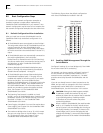
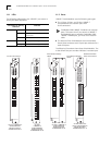
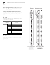
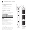
15.2 Ports
FDDI SwitchModules support the following port
configurations:
■
2-Port FDDI SwitchModule
—
Supports 2 DAS (A/B)
ports with MIC connectors.
■
12-Port FDDI Concentrator SwitchModule
— Supports
2 DAS (A/B) ports and 8 Master (M) ports with
MIC connectors. Each side of the FDDI Concentrator
SwitchModule is a Dual Attachment Concentrator
(DAC), which is composed of 4 M ports and an A and B
port pair that is connected to a single MAC.
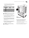
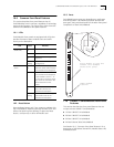
15.3 Optical Bypass Connector
FDDI SwitchModules support one optical bypass connector
per port. Use the optical bypass connector to preserve a
dual FDDI ring in the event of a station failure. The optical
bypass connector accepts an optical bypass switch of type
AMP FOTP-34 Method B using a mini-DIN connector.
Port Status LED State Indicates
Green On Port is enabled and ring is operational.
Green Blinking Port is connecting.
Off Port or port functions are disabled.
FDDI Port Status LEDs
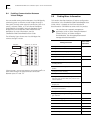
12-Port FDDI
Concentrator
SwitchModule
Model Number
3C96612M-FC-A
2-Port FDDI
SwitchModule
Model Number
3C96604M-F-A
MIC
connectors
6604M-F-A
1B
2B
1A
2A
1A
1B
OPTICAL
BYPASS 2
OPTICAL
BYPASS 1
2A
2B
6612M-FC-A
1M
3M
2M
4M
1B
2B
2M
4M
2A
1M
3M
OPTICAL
BYPASS
OPTICAL
BYPASS
1A
1A
1B
2A
2B
2-
1M
2-
2M
1-
1M
1-
2M
2-
3M
2-
4M
1-
3M
1-
4M