


C
ORE
B
UILDER
®
5000 S
WITCH
M
ODULE
Q
UICK
S
TART
AND
R
EFERENCE
7
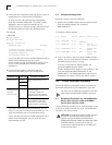
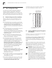
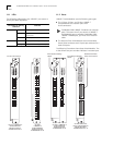
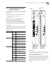
The following figure shows the hub configured with a
network management station on the LAN that is attached
to SwitchModule port 2.6:
To manage the hub from the network management station
in the previous figure:
1
Configure IP settings for virtual bridge 1 using the
commands in the following example (values shown are
sample values):
> set ip subnet_mask ff.ff.ff.00 vbridge 1
> set ip ip_address 141.102.3.131 vbridge 1
>
set
ip default_gateway
141.102.3.2
vbridge 1
Assigning an IP address to a virtual bridge automatically
enables the virtual bridge interface to the DMM.
2
Save the settings as follows:
> save ip
You can now access the DMM from the network
management station. You can also send SNMP and RMON
requests to the DMM. From the DMM, you can manage
any network, virtual bridge, or module in the
CoreBuilder 5000 hub.
If you have multiple subnetworks in your network, and
you want to manage the hub in-band from each
subnetwork, you must configure IP settings for each
subnetwork.
If you already have an in-band connection to the DMM
and if you still want to add in-band connectivity through a
SwitchModule port, do one of the following:
■ Before you establish an in-band DMM interface through
the SwitchModule, assign the virtual bridge an IP
address that is on a unique subnetwork.
■ Disable the existing in-band DMM interface.
SwitchModules in
slots 2, 3, and 4
NMS
LAN
DMM in
slot 1
For more information about IP configuration, see the
CoreBuilder 5000 SwitchModule User Guide
on the
DocsOnCD
documentation CD-ROM that comes with this
product.
8.3 Creating an Additional Virtual Bridge
A virtual bridge is a user-defined group of SwitchModule
ports. This group of ports operates as a single logical
bridge.
You can segment your network into more than one virtual
bridge by creating new virtual bridges. You can assign any
port on any SwitchModule to the new virtual bridge.
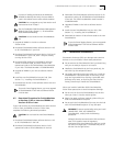
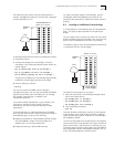
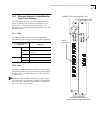
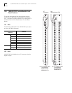
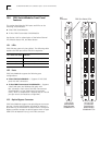
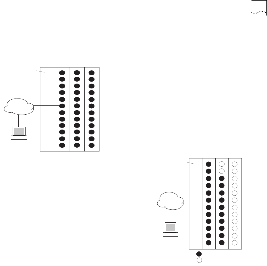
The following figure shows a SwitchModule network that
is configured with two virtual bridges:
To create the configuration in this figure:
1
Enter the commands in the following example (values
shown are sample values):
> set bridge_port 3.1 vbridge 2
> set bridge_port 3.2 vbridge 2
> set bridge_port 4.all vbridge 2
2
Save the settings as follows:
> save all
The new network configuration consists of two separate
virtual bridges. Each virtual bridge maintains a separate
Spanning Tree configuration. All ports on virtual bridge 2
are enabled by default.
The two virtual bridges that are described in this example
cannot send traffic to one another at this point without an
external connection. (See Section 8.4.) However, you can
manage all ports on both virtual bridges using the DMM or
other supported network management software, such as
3Com Transcend
®
Network Control Services.
SwitchModules in
slots 2, 3, and 4
NMS
LAN
DMM in
slot 1
Virtual bridge 1
Virtual bridge 2