


C
ORE
B
UILDER
®
5000 S
WITCH
M
ODULE
Q
UICK
S
TART
AND
R
EFERENCE
3
For ease of reading and because the DMM and
A/DMM are basically the same, the term DMM is
used in this release note to refer to both modules.
CAUTION:
Do not upgrade to any later version until
instructed to do so in Step 5.
See the CoreBuilder 5000 Distributed Management
Module User Guide, Chapter 11, for information
about DMM downloading.
CAUTION:
Do not install the new SwitchModules
yet.
1
Upgrade all DMMs in the hub to software
Version v5.00.
2
Download SwitchModule boot software Version v1.05
to all SwitchModules in your hub.
3
Download SwitchModule software Version v3.00 to all
SwitchModules in your hub, even if they are already
running Version v3.00.
4
Download ATM Backbone SwitchModule software
Version v2.05 boot code, and then Version v3.00
operational code to all ATM Backbone SwitchModules
in your hub. The Model Number is 3C96602M-MOD.
5
Upgrade all DMMs in your hub to software Version
v6.00.
6
Install the new SwitchModule into your hub. (See
Section 7.0, "Installing the SwitchModule".)
7
Download the Version v3.00 software code to the new
SwitchModule.
To use the Frame Tagging feature, you must upgrade
all SwitchModules in the hub to software Version
v3.00 or later.
4.2 Download Procedure for SwitchModules
at Version v2.02 or Later and DMMs at
Version v5.00 or Later
If your hub contains any SwitchModules that are at Version
v2.02 or later, and DMMs at Version 5.00 or later,
complete the following download procedure:
CAUTION:
Do not install the new SwitchModules
yet.
1
Download SwitchModule boot software Version v1.05
to all SwitchModules in the hub.
2
Download SwitchModule software Version v3.00
operational code to all SwitchModules in the hub.
3
Download ATM SwitchModule software Version v3.00
operational code to all ATM Backbone SwitchModules
in the hub. The ATM SwitchModule model number is
3C96602M-MOD.
4
Upgrade all DMMs in the hub to software Version
v6.00.
5
Install the new SwitchModule into your hub. (See
Section 7.0, "Installing the SwitchModule".)
6
Download the Version v3.00 software code to the new
SwitchModule.
To use the Frame Tagging feature, you must upgrade
all SwitchModules in the hub to software Version
v3.00 or later.
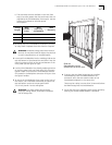
5.0 Installation Precautions
Electrostatic discharge (ESD) can damage static-sensitive
devices on circuit modules. Follow these precautions:
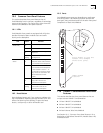
■ Do not remove the SwitchModule from its antistatic bag
until you are ready to inspect or to install it.
■ Handle the SwitchModule by the front panel only; do
not hold it by the component board.
■ Use proper grounding techniques when you install the
SwitchModule. These techniques include using a foot
strap and a grounded mat, wearing a grounded static
discharge wrist strap, or touching the metal rack or
frame just before you handle the SwitchModule.
When you handle CoreBuilder 5000 SwitchModules,
follow these precautions to avoid component damage:
■ Do not twist or force the SwitchModule into the hub
when you insert it into the module guides.
■ Match the upper and lower module guides while you
slide the SwitchModule into place.
■ Do not push the SwitchModule all the way into the hub
until the SwitchModule ejectors (if any) are open.
WARNING:
To ensure optical safety when you install
10BASE-FB/FL, FDDI, and 100BASE-FX
SwitchModules, comply with the following
precaution:
Although the data communication LEDs and Lasers
used in this product meet the regulatory
requirements for casual exposure to the eye, as with
any source of bright light, it is advised that you do
not look into the light source.