


Connecting PGND Wire and Power Cord 57
Step 6: Align the mounting ears with the square holes in the posts of the cabinet,
and fasten the screws in the holes to fix the switch in the cabinet.
Connecting PGND
Wire and Power Cord
Connecting PGND Wire
c
CAUTION: For the safety of operators and equipment, the switch must be well
grounded. The resistance reading between switch chassis and the ground must be
less than 1 ohm.
Common grounding environment
Step 1: Remove the screw from the grounding hole in the switch chassis.
Step 2: Wear the connector of the PGND wire accompanied with the switch on
the grounding screw.
Step 3: Insert the grounding screw into the grounding hole and screw it down.
Step 4: Connect the other end of the ground wire to the ground bar of the switch.
n
Generally, the cabinets installed in equipment rooms are equipped with ground
bar. In this case, you can connect the PGND wire of the switch to the ground bar
for it.
Other grounding environment
Following are some methods for grounding the switch in different grounding
environments that you are likely to encounter when installing the switch at
different places.
n
Rather than specifying the switch model or showing the actual location of the
switch power input or grounding screw, the following figures are primarily
intended for illustrating the switch grounding, either via grounding screw or
power input, in specific grounding environments.
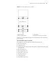
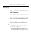
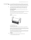
■ If a ground bar is available, attach one end of the yellow-green PGND wire of
the switch to a grounding bolt of the ground bar and fasten the captive nuts.
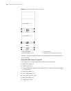
Note that the fire main and lightning rod of a building are not suitable for
grounding the switch. The PGND wire of the switch should be connected to
the grounding device in the equipment room. (For the Switch 8800 Family, the
grounding screw is on the rear panel. Connect it as illustrated in
Figure 37).