


62 CHAPTER 4: SWITCH INSTALLATION
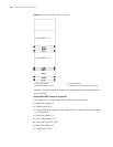
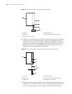
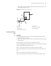
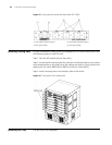
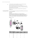
Figure 43 Front panel of external PoE Power Rack (3C17509)
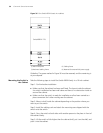
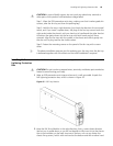
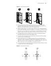
Installing Cabling Rack For your convenience, cabling racks are shipped with the Switch 8800 Family. Take
the following steps to install the rack.
Step 1: Face the I/O module slots of the switch;
Step 2: Attach the left mounting ear (the one with an elliptical hole on one surface
and a recessed hole on the other) onto the cabling rack and fix it with screws (one
cabling rack for Switch 8807/Switch 8810 and two for Switch 8814);
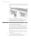
Step 3: Install mounting ears onto the both sides of the switch.
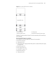
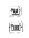
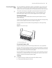
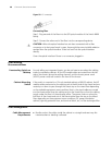
Figure 44 The position of the cabling rack
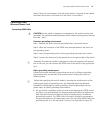
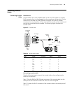
Installing Fan Tray The fan tray is hot swappable.
(1) DC output terminal: NEG(-) (2) DC output terminal: RTN(+)
(3) AC input switch (4) AC input socket