


Hardware Maintenance 83
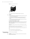
Removing a module
Step 1: Wear the ESD-preventive wrist strap and unscrew the captive screws on
the module with a flathead screwdriver.
Step 2: Hold the ejector levers on the module with both hands and press them
outward to separate the locking pin of the module from the backplane.
Step 3: Gently pull the module out of the slot along the guides.
Figure 59 Removing a Module
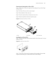
Installing a Module
Step 1: Wear the ESD-preventive wrist strap and unscrew the mounting screws
fixing the blank filter panel in the slot where you want to install the module, and
remove the blank filler panel.
Step 2: Hold the ejector levers of the card with both hands and pull them outward,
align the card with the guides in the chassis, and slide it gently into the slot until
its positioning pin touches the positioning hole in the chassis.
Step 3: Pull the ejector levers inward to lock the positioning pin of the card into
the positioning hole in the chassis.
Step 4: Fasten the captive screws to fix the card.
Figure 60 Installing a Module
Replacing the Fan Tray
c
CAUTION: Do not touch naked wires, terminals or the switch parts where
dangerous voltage warning is given to avoid bodily injury.
Required tools
■ ESD-preventive wrist strap
■ Screwdriver
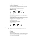
Replacing the fan tray
Step 1: Wear the ESD-preventive wrist strap. Screw off the captive screws on both
sides of the fan tray. Pull the fan tray outward with one hand contacting the
switch top and the other hand around the handle of the fan tray to separate the
fan tray positioning pin from the backplane.