


64 CHAPTER 4: SWITCH INSTALLATION
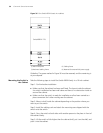
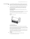
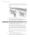
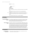
at the front panel, and then slide it smoothly along the guide rail to the slot, until
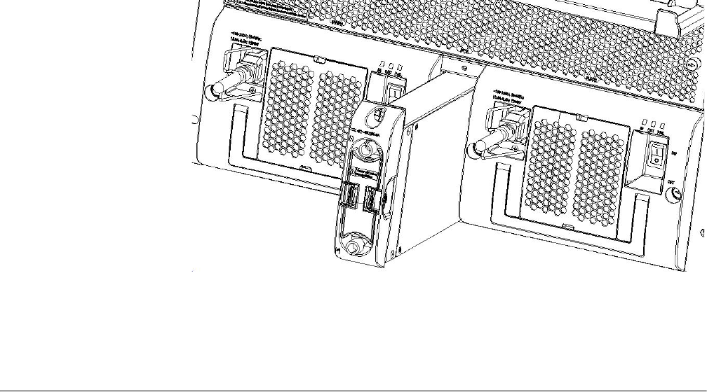
it fits into the chassis, with its plug fully touching the socket inside the chassis. See
Figure 46.
Figure 46 Install PoE lightning protection box
3 Fasten the screw on top of the PoE lightning protection box.
n
Generally, the PoE lightning protection box is shipped with the chassis of the
switch you ordered. So you need not to install the box. The above installation
procedure is needed only when you are changing the fan frame.
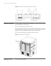
Installing I/O modules The I/O modules of the Switch 8800 Family are hot-swappable.
Step 1: Wear the ESD-preventive wrist strap, making sure that you have grounded
it well. Take the I/O module out of the packing bag.
Step 2: Unscrew the mounting screws holding the blank filler panel in the slot
where you plan to install the I/O module, and remove the panel from the slot.
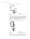
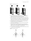
Step 3: Hold the ejector levers on the fan tray with both hands and pull them
outward. Align the I/O module with the guides in the chassis and slide it gently
into the slot until the positioning pin of the I/O module touches the hole in the
chassis.
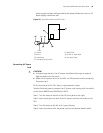
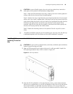
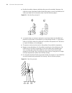
Step 4: Pull the ejector levers inward, locking the positioning pin into the hole.
Step 5: Fix the I/O module by fastening the mounting screws on the I/O module
with a screw driver.
n
Put the removed blank filler panel away for future use.
For the Switch 8800 Family, the Application Module can be installed in the I/O
module slot in the same way as installing the I/O module board.