


Connecting PGND Wire and Power Cord 61
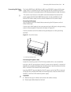
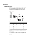
Connecting PoE Power
Cord
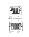
The Switch 8807/Switch 8810/Switch 8814 uses PSE4500-A external PoE power
supply, which is connected to the switch through the PoE module at the front
bottom of the switch to provide power to PDs (powered devices) under the switch.
n
This section only focuses on the cable connection between the external PoE
power supply and the Switch 8800 Family switch. For the installation of the
external PoE power supply, see the manual shipped with the power supply.
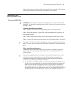
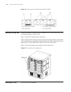
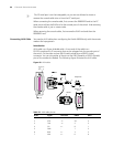
Grounding PoE chassis
You must ground the PoE chassis before connecting the PoE power cord to it.
Follow these steps:
Connect the 6 AWG cable of the wiring terminal (with M6 hole) to the grounding
screw on the rear panel of the switch, as shown in
Figure 42.
Connect the other end of the cable to the grounding bar or other grounding
terminals.
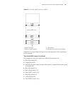
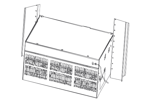
Figure 42 Ground PoE chassis
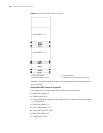
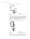
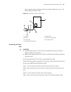
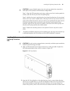
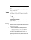
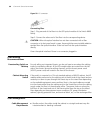
Connecting PoE power cable
Loosen the mounting screw of the PoE entry module with a cross screwdriver.
Insert the -48V OT terminal (blue) of the DC power cord to the NEG (-) terminal of
the PoE entry module and fasten the mounting screw; insert the other end to the
NEG (-) terminal of the external PoE power supply.
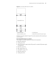
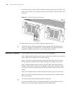
Insert the GND OT terminal (black) of the DC power cord to the RTN (+) terminal
of the PoE entry module and fasten the mounting screw; insert the other end to
the NEG (-) terminal of the external power supply.
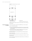
c
CAUTION:
■ Observe the signs on devices and connect the cables correctly.
■ Choose right cables based on the load.
(1) Chassis grounding screw