


ATM Cabling
113
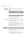
*Maximum attenuation includes cable attenuation and the loss induced
by other components such as connectors, splices, and the mating of
unlike fiber types. Although some 2 km cable plants have a total
attenuation of less than 11.0 dB, the 2 km interstation distance must be
maintained to comply with modal bandwidth requirements.
Calculating Insertion
Losses for Unlike
Fibers
If unlike fibers are mated in the cable plant, calculate insertion losses to
be certain that the cable plant does not exceed the maximum attenuation
value listed in Table 25. To calculate the insertion loss, consider the types
of fiber in the cable plant and the connectors or splices used to join them.
Compare the result to the maximum attenuation value listed in Table 25.
If the result is greater than the value in the table, use only like fibers in the
cable plant.
Refer to Table 27 for the insertion losses of the fibers themselves. Use
Table 28, which lists the losses for connectors, cables, and splices, if the
specifications for these components are not available.
Use Table 27 for fiber-to-fiber connections only, not for power launched
from a transmitter.
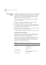
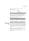
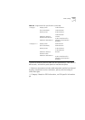
Maximum distance between nodes 2 km
Output power (from transmitter) 19 dB minimum
14 dB maximum
Receive power 30 dB minimum sensitivity
14 dB maximum sensitivity
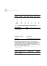
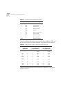
Table 26
Alternate Multi-mode Fiber Types
Core (
µ
m) Cladding (
µ
m) Numerical Aperture
50 125 0.20
50 125 0.22
85 125 0.28
100 140 0.29
Table 25
Standard Multi-mode Fiber Specification (continued)