


38
C
HAPTER
4: I
NSTALLING
AND
C
ONNECTING
C
ORE
B
UILDER
M
ODULES
e
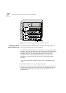
Transfer the RS-232 cable to the service port of the redundant switch
module.
f
Repeat step d)
g
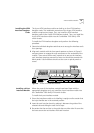
Transfer the RS-232 cable to the console port of the main switch
module.
Hardware Redundancy Setup
2
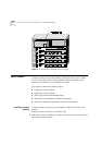
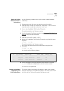
Set up the main switch module using the Integrated Fast Setup (see
“Integrated Fast Setup” on page 56
). Do not reboot the switch from the
Integrated Fast Setup procedure (answer “no” to the prompt).
The main menu appears.
3
Wait for one minute to allow the configuration data to transfer from the
main switch module to the redundant switch module.
4
Reboot the switch using the LMA menu sequence: (1) SYS / (7) RBO. This
causes the configuration data to be recorded in flash memory and also
causes the redundant switch module to become the main switch module.
5
After the switch reboots, answer “no” to the prompt: “Do you wish to
erase the setup parameters”.
6
Run the Integrated Fast Setup procedure as in step 2) to verify that the
setup parameters have been transferred correctly to the second switch
(the Integrated Fast Setup procedure now displays the setup parameters
resident in the second switch module). Press Enter repeatedly to verify
these parameters; do not enter new values.
7
Verify that the ELAN names in the LECS database are identical in both
switch modules. Use menu item (2) LEM/(1) LCS/(5) LNT to check that the
LECS database of the second switch includes the ELAN name of the first
switch. For example, Elan6666_0 - Elan6666_15
NMS-Based LANE Redundancy Setup
8
Verify connectivity between the switch module and the NMS station by
pinging the switch module from the NMS station.
9
Load the Transcend application and open the Wizard Tool from the
ATMvLAN tool bar
10
Open the Backbone and Services Window.
11
Configure the LECS order as desired and press the Apply button.
12
Configure the LECS database. Add all the primary and redundant ELAN
names desired to the LECS database and press Apply. Make a list of the