


Switch Module
35
Setting up Switch
Module Hardware
Redundancy
Use the following procedure to set up the switch module hardware
redundancy.
1
Designate and mark the main and redundant switch modules.
2
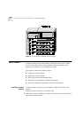
Insert the switch module you marked as “redundant” in slot 2. Do not
insert the switch module you marked as “main” yet.
3
Turn on the CoreBuilder 7000 family ATM switch.
The switch module in slot 2 becomes active.
4
Run the Integrated Fast Setup procedure (see “Integrated Fast Setup” on
page 56.) using the LMA command
(9) FST
5
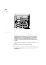
Insert the main switch module in slot 1.
6
Reboot the CoreBuilder 7000 family ATM switch using the LMA menu
sequence:
(1) SYS / (7) RBO
.
The switch module in slot 1 becomes active.
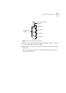
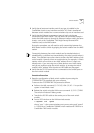
7
Verify main and redundant switch module status using the LMA
command:
(1) SYS / (4) SWM
You should see the following display.
8
Run the Integrated Fast Setup procedure using the LMA command
(9) FST
to verify the configuration in the main switch module.
The switch is now operational.
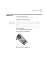
Setting up Hardware
Redundancy and
LANE Redundancy
This section presents a procedure for setting up both switch module
hardware redundancy and LANE redundancy in the same session. Both
the LMA and the Transcend Enterprise Manager are used.
Slot id Slot status Switch type Switch mode Memory size
------- ----------- ---------------- ------------ -----------
1 Occupied 16x16 ATM switch Active 8M
2 Occupied 16x16 ATM switch Redundant 8M