


36
C
HAPTER
4: I
NSTALLING
AND
C
ONNECTING
C
ORE
B
UILDER
M
ODULES
General Description of the Procedure
The following is a general description of the procedure for orientation
purposes only. When you perform the procedure, use the detailed steps
in the following sections.
1
Install both switches in chassis and run CFGFRMAT.BAT on each one.
Connect Ethernet ports of each switch module and install at least one
interface card in the chassis.
2
Configure the first switch using the Integrated Fast Setup of the LMA and
do not reboot the switch in the Integrated Fast Setup.
3
Reboot the switch after one minute using the LMA menu.
4
Answer “no” to the prompt “Erase the setup parameters?” and use the
LMA to check that all configuration parameters (i.e., database, IP, NNI
etc.) have passed successfully to the second switch module.
5
Configure LANE redundancy in the first switch using the Transcend
Backbone and Services Setup window and close the window when
finished.
6
Reboot the switch after one minute
7
Configure LANE redundancy in the second switch module using the
Transcend Backbone and Services Setup window and close the window
when finished.
8
After one minute use the MIB browser to check the LECS order list and
the Backbone and Services Setup window to check the LECS database.
9
Reboot the box.
10
Check the second switch using the MIB browser to check the LECS order
list and the Backbone and Services Setup window to check the LECS
database.
Preparatory Steps
Carry out the following preparatory steps.
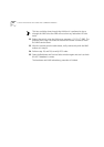
1
Install main and redundant switch modules in the switch module slot 1
and slot 2 respectively (see“Installing a Switch Module” on page 32
). Do
not run the Integrated Fast Setup yet.
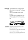
Each time the switch is rebooted during this procedure the cards change
roles. The main card becomes the redundant card and vice versa. The
main card can always be identified by its ACT LED flashing once every
two seconds. The ACT LED of the redundant card flashes at a lower rate.