


5
P
OWER
-O
N
This chapter describes the system states of the CoreBuilder
®
7000 family
ATM switch including power-on and some basic diagnostic information to
help you verify normal operation of your CoreBuilder system.
This chapter describes the following topics:
■
System States
■
System Power-on
■
4-Port Interface Module LEDs
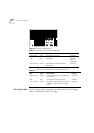
System States
This section describes the different system states of the 8-Port Board and
how they are indicated on the LED display.
The system states are:
■
Power-on
■
Normal operation
■
Hardware fault
■
Software fault
■
No power to unit
System States and
Switching Module
LEDs
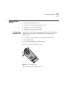
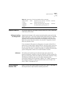
LED indicators are located on the front panels of the CoreBuilder 7000, its
power supply, switching modules, and interface modules. These LEDs
indicate the current system state of the CoreBuilder unit and its
components. Front panel LEDs can be extremely useful in determining the
cause of specific problems.
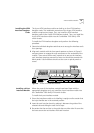
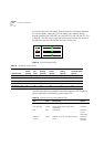
The system state in which the CoreBuilder 7000 unit is currently
operating is displayed by the switching module system status LEDs.
Referring to Figure 9, these are the three LEDs: PWR, FAIL, and ACT(ive)