


114
A
PPENDIX
D: C
ABLING
R
EQUIREMENTS
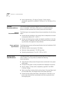
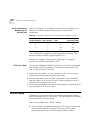
Example
Suppose that a link consisting of one km of 62.5/125 fiber with a
maximum attenuation rating of 1.75 dB/km is transmitting into one km
of 50/125 fiber with a maximum attenuation rating of 3 dB/km. The
fibers are joined using a fusion splice rated at 0.3 dB and the link contains
one in-line ST connector rated at 0.6 dB.
The following calculation would arrive at the link loss attenuation value
for this linked fiber:
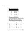
Table 27
Insertion Losses for Mating Unlike Fiber Types - Transmitting Fiber
Receiving
Fiber Size
Numerical
Aperture
50
µ
m 50
µ
m 62.5
µ
m 85
µ
m 100
µ
m
0.20 0.22 0.275 0.26 0.29
50 µm 0.20 0.0 0.4 2.2 3.8 5.7
50 µm 0.22 0.0 0.0 1.6 3.2 4.9
62.5 µm 0.275 0.0 0.0 0.0 1.0 2.3
85 µm 0.26 0.0 0.0 0.1 0.0 0.8
100 µm 0.29 0.0 0.0 0.0 0.0 0.0
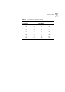
Table 28
Typical Losses for Typical Connectors, Cables, and Splices
Type of Insertion Loss
SC connector .6 dB
ST connector (ceramic) .6 dB
ST connector (plastic) 1.0 dB
ST connector (stainless steel) .7 dB
62.5/125 cable 1.0 to 3.0 dB maximum per km, depending
on cable quality (nominal 2.0 dB)
8/125 cable .5 dB/km (AT&T Lightguide)
Bypass switch (currently not
available in single mode)
2.5 dB maximum
Fusion splice 1 to 3 dB depending on type used (use .3 dB)
62.5
µ
m
cable loss
+ 50
µ
m
cable loss
+ splice
loss
+ ST con-
nector loss
+ insertion
loss
*
* for mating unlike fiber types
= Total link
attenuation
1 km(1.75
dB/km)
+1 km(3
dB/km)
+0.3 dB +0.6 dB +2.2 dB =7.85 dB