


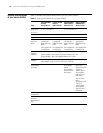
14 CHAPTER 1: INTRODUCING THE SWITCH 4500G FAMILY
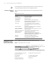
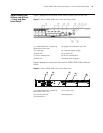
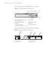
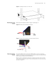
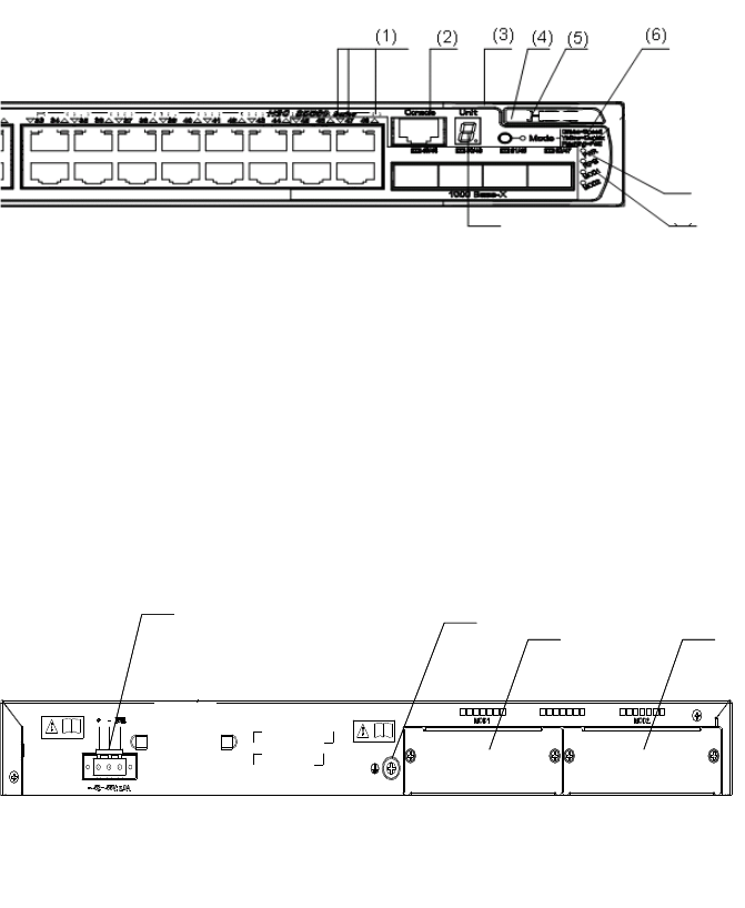
Figure 7 displays the Switch 4500G PWR 48-Port unit’s front panel.
Figure 7 Switch 4500G PWR 48-Port Unit’s Front panel
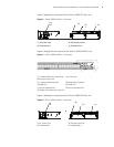
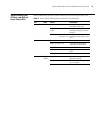
Figure 8 describes the Switch 4500G PWR 48-Port unit’s rear panel.
Figure 8 Switch 4500G PWR 48-Port Unit’s Rear Panel
(1) 10/100/1000 BASE-T autosensing
Ethernet port status LEDs
(2) Console port
(3) 7-segment digitron display (4) Mode switching button
(5) Mode LED (6) Power LED
(7) LED for extended slot 1 (8) LED for extended slot 2
(9) Gigabit SFP Combo port status LED
(1) AC power input (2) Grounding terminal
(3) Extended slot 1 (4) Extended slot 2
(7)
(8)
(9)
(1) (2)
(3)
(4)
(5)
(1) (2)
(3)
(4)
(5)
(2)
(3)
(4)