


Chapter 3 63
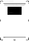
Disassembly Procedure Flowchart
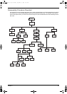
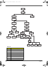
The flowchart on the succeeding page gives you a graphic representation on the entire disassembly sequence
and instructs you on the components that need to be removed during servicing. For example, if you want to
remove the system board, you must first remove the keyboard, then disassemble the inside assembly frame in
that order.
Start
Battery
RAM Door HDD Module
Hinge Caps
ODD module
Memory
Ax2
Bx2
ODD
Holder
ODD
Assembly
Fx4
Ex2
ODD Door
ODD PCB
Board
ODD
Drive
HDD
Cover
HDD
Assembly
Hx4
HDD
Carrier
HDD
Connector
HDD
Keyboard
Dx4
Middle Cover
Main Unit
(See Next
Page)
LCD Module
Bx1
Dx9
Cx5
Fx1
LCD Bezel
VGA
Shielding
Bx4
VGA
Board
Jx1
Inverter
Wire
Inverter
Board
LCD
Panel
Bx4
Jx8
LCD
brackets
LCD
LCD
Coaxial
Cable
Ax2
TM420.book Page 63 Monday, September 23, 2002 10:27 AM