


Chapter 3 43
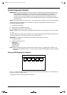
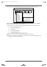
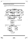
Disassembly Procedure Flowchart
The flowchart on the succeeding page gives you a graphic representation on the entire disassembly sequence
and instructs you on the components that need to be removed during servicing. For example, if you want to
remove the system board, you must first remove the keyboard, then disassemble the inside assembly frame in
that order.
START
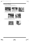
Middle Cover
(short)
Hinge caps Modem CoverDIMM Door
Battery Pack
LED Board Cable
from M/B
Battery Door
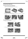
DIMM Module
Modem Board
Middle Cover
(Long)
LED Board
LCD & Inverter
board
LCD FPC Cable
Inverter Board
86.1A522.140 *2
Screw MACH PAN
M2*14L
86.1A353.135
*2 Screw
MACH PAN
M2.5 *13.5L
86.9A523.6R0 *5 Screw
M2.5*6L B/ZN
86.9A522.4R0 *2 Screw
MACH PAN M2*4L
86.9A522.4R0 *2 Screw
MACH PAN M2*4L
86.5A524.4R0 *4 Screw
M3*4L
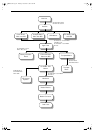
Keyboard
LCD FPC Cable
from M/B
Main Unit
(see next page)
LCD Module
LCD Bezel
LED Board
Cable
LCD Panel
505-1.book Page 43 Thursday, November 4, 1999 4:36 PM