


Setup File Reference SDR2-USB Configuration Guide rev 1.0
24
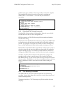
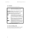
5.3 Functions
Table 5.1 describes the functions of the J4 remote connector.
V
DD
(3.3VDC) Regulated low-current voltage output. Use for deasserting
active-low inputs and driving LED indicator outputs.
GND (0 VDC) Signal ground. Use for asserting active-low inputs.
Momentary record input. Function is similar to front-panel
record button. To use, connect a momentary pushbutton
switch between this contact and GND.
Force-record input. To use, connect a toggle switch
between this contact and GND. When closed, the
SDR2-USB will always enter record mode.
Fault condition indicator output. Function is similar to the
front-panel Fault indicator. When low, indicates an
unrecoverable error has occurred in the SDR2-USB. To
use, connect an LED’s cathode to this contact and its anode
to V
DD
via a current-limiting resistor. Limit current to 10 mA
max.
Data indicator output. Function is similar to the front-panel
Data indicator. Pulses momentarily low to indicate data
reception in the SDR2-USB. To use, connect an LED’s
cathode to this contact and its anode to V
DD
via a current-
limiting resistor. Limit current to 10 mA max.
Recording indicator output. Function is similar to the front-
panel Record indicator. Driven low when the SDR2-USB is
recording data to an open file. To use, connect an LED’s
cathode to this contact and its anode to V
DD
via a current-
limiting resistor. Limit current to 10 mA max.
Table 5.1. J4 remote control port pin functions.
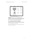
5.4 Pinout and Mating Cable
The J4 connector is a 2mm 10-pin connector housing that mates to a Hirose
DF11-10DS-2C shell (Digi-Key part number H2023-ND). A pre-built J4
cable is available from Acumen Instruments Corporation on request.
REC_BUTTON
REC_TOGGLE
FAULT
DATA
RECORD