


SDR2-USB Configuration Guide rev 1.0 J4 Remote Control Port
25
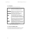
Contact Function Direction Wire Color
1 V
DD
(3.3 VDC) -
2
GND (0 VDC)
Black
3
input Blue
4 input Grey
5
output Yellow
6 no connect -
7
output Orange
8 output Green
9 V
DD
(3.3 VDC) -
10 GND (0 VDC) -
Table 5.2. J4 remote control port pinout.
J4 mating plug (shell): Hirose DF11-10DS-2C (Digi-Key part number
H2023-ND)
For use with DF11 crimp contacts e.g. DF11-2428SCA (Digi-Key part number
H2300-ND) or pre-crimped wires (Digi-Key part number H3BXG-101LL-CW
where LL=length in inches, C=color code, W=wire gauge code).
5.5 Force-Record Shunt Installation
The SDR2-USB can be forced into record mode any time power is applied
and USB storage is present. To use this mode, install a 2mm shunt between
J4 pins 4 (REC_TOGGLE) and pin 2 (GND).
A good choice of shunt is Norcomp part number 810-002-SP2L001 (Digi-
Key part number SP2-001E-ND).
REC_BUTTON
REC_TOGGLE
FAULT
DATA
RECORD