


SDR2-USB Configuration Guide rev 1.0 Serial Port Basics
33
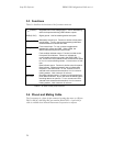
NOTE: Most serial
devices format of eight
data bits, no parity,
and one stop bit
(8N1).
To transfer data asynchronously, the UART frames the 8 data bits between a
stop bit and a start bit. The start bit is always a zero, while the stop bit is
always a one. So, a byte of data sent serially is made up of 10 bits instead of
the usual 8.
Asynchronous serial devices can communicate using 7 or 8 data bits, and 1,
1½, or 2 stop bits. To further complicate matters, devices can also employ a
parity bit instead of an eighth data bit to check for errors. Even parity
systems transmit a one when the sum of the seven bits is an even number,
while odd parity systems transmit a one when the sum is odd. Still more
exotic systems may specify “mark” or “space” parity, where the parity bit is
always a one or zero, respectively.
What does all of this mean? Device vendors usually specify their data rate
and format using statements like “9600, 8N1”, which translates to 9600 bps,
8 data bits, no parity, and 1 stop bit or “19200, 7E1”, which translates to
19200 bps, 7 data bits, even parity, and 1 stop bit.
A.3.2 DTE and DCE
The RS-232 specification defines two classes of devices: data terminal
equipment (DTE) and data communication equipment (DCE). Your
computer’s serial port is configured for DTE operation, since the computer
acts as a terminal. Modems and many other serial devices are configured as
DCE, since they are communications equipment.
What’s the difference? A DTE device’s TD signal means “I transmit data on
this line.” A DCE’s TD signal can be read “You (the DTE) transmit data to
me on this line.” A DTE’s RD signal means “I receive data on this signal
line.” A DCE’s RD line means, “You, the DTE, will receive the data I
transmit on this signal line.” Sound confusing?
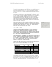
A look at a the DB9 connector pinouts and signal direction with respect to
DTE (e.g. your computer) makes things a little more clear.
pin number
signal name
25-pin 9-pin direction
transmitted data
TD
2 3 DTE→DCE
received data
RD
3 2 DTE←DCE
request to send
RTS
4 7 DTE→DCE
clear to send
CTS
5 8 DTE←DCE
data terminal ready
DTR
20 4 DTE→DCE
data set ready
DSR
6 6 DTE←DCE
data carrier detect
DCD
8 1 DTE←DCE
ring indicator
RI
22 9 DTE←DCE
signal ground
GND
7 5
Table A.2. Pinouts for 9-pin and 25-pin serial connectors.
The cable that connects DTE devices (such as your computer) and DCE
devices (such as your modem) is simple. It connects the TD pin to TD, pin
RD to RD, etc. A cable that connects DTE to DTE or DCE to DCE must
connect the TD to RD and RD to TD. This cable is referred to as a null