Serial Port Basics SDR2-USB Configuration Guide rev 1.0
34
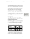
modem cable because it can connect two terminals (DTE’s) without the use
of modems (DCE’s). Note that GND pins are always connected.
Most devices have female connectors (DB9 or DB25) if they are configured
for DCE operation and male connectors if they are configured for DTE
operation, but this is not always the case.
There is a simple trick for determining whether a device is DTE or DCE.
Connect a voltmeter’s ground line to the connector’s GND pin. Then, probe
the voltage on the TD and RD pins. If the TD pin voltage is small (-
3V<Vin<+3V), the device is configured to receive data on the TD pin, and
thus is a DCE device. Likewise, if the RD pin voltage is small, the device is
receiving data on the RD pin, and thus is DTE.
A.3.3 Handshaking
Handshaking signals by the receiving device to tell the transmitter “I am
ready for data” or “I am not ready for data.” These signals are optional: the
receiver may always be ready for data or may choose to simply discard data it
couldn’t process.
A DTE device asserts the “request to send” (RTS) signal when it is ready to
receive data and deasserts it when it cannot accept data. Likewise, a DCE
device asserts “clear to send” (CTS) when it is ready to receive data. The
RTS and CTS signals form a handshaking pair, and their use constitutes
RTS/CTS handshaking.
The “data terminal ready” (DTR) signal, asserted by the DTE, and the “data
set ready” (DSR) signal, asserted by the DCE serve similar functions and
constitute DTR/DSR handshaking. A DTE or DCE devices may employ
either or both forms of handshaking. Often, deasserting RTS or CTS signals
“micro” events, such as a buffer that is full but will be empty soon, while
deasserting DTR or DSR may signal “major” events such as that power has
not been applied.
RTS/CTS handshaking and DTR/DSR handshaking are both referred to as
hardware handshaking. Another form of handshaking, XON/XOFF or
software handshaking, requires that the receiver send a character (Control-S,
ASCII 19) to halt data transfer and another character (Control-Q, ASCII
17) to resume transfer. Although this method eliminates the need for the
RTS, CTS, DTR, or DSR signals, it suffers from slow response time by the
receiver and renders 2 characters of the 256-character ASCII set unusable.
A.3.4 Voltage levels
For noise immunity and long cable lengths, RS-232 devices convert
TTL/CMOS-level signals (0V=logic zero, +5V or +3.3V=logic one) to
higher voltage bipolar signals. For the TD and RD signal lines, RS-232
devices use a voltage between –3V and –25V to transmit a one and a voltage
between +3V and +25V to transmit a zero. For the other signal lines (RTS,


