


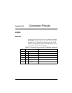

Appendix B. Connector Pinouts
B-2 TDU 120e User Manual 61202156L2-1
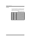
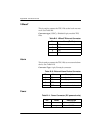
Control In/Chain In
This is used as an RJ-45 port for connection to a computer
or modem (Control In) or to another TSU/TDU family
multiplexer or TSU 100 (Chain-In). See Table B-3 for the
pinout for the control/chain-in connector.
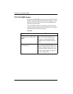
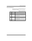
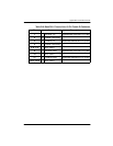
Table B-2. Network Pinout of the Male 15-Pin D-Connector
Pin Name Description
1 T TX DATA TIP Sends data toward the Network
2 FG FRAME GROUND
3 T1 RXDATA-TIP Receives data from the Network
4 FG FRAME GROUND
5,6,7,8 UNUSED
9 R TXDATA-RING Sends data toward the Network
10 UNUSED
11 R1 RXDATA-RING Receives data from the Network
12,13,14,15 UNUSED
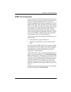
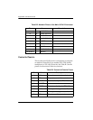
Table B-3. Control In/Chain In Pinout
Pin Name Description
1 GND Ground - connected to unit chassis
2 RTS Request to send - flow control
3 RXDATA Data received by the TDU 120e
4 UNUSED
5 TXDATA Data transmitted by the TDU 120e
6 Ext Alarm A When grounded, generates Alarm A
7 Ext Alarm B When grounded, generates Alarm B
8 CTS Clear-to-send-flow control