612022156L2-1 TDU 120e User Manual xxiii
List of Tables
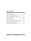
Table 4-1. Alarm Message Display........................................................................ 4-4
Table 5-1. Normal Mode of Operation................................................................ 5-25
Table 8-1. Unit Access Table Commands ............................................................ 8-3
Table B-1. Network Pinout of the 8-Pin Modular Connector............................B-1
Table B-2. Network Pinout of the Male 15-Pin D-Connector ............................B-2
Table B-3. Control In/Chain In Pinout .................................................................B-2
Table B-4. Chain-Out Pinout ..................................................................................B-3
Table B-5. Craft Port Pinout....................................................................................B-4
Table B-6. V.35 Pinout for Nx56/64 DTE .............................................................B-5
Table B-7. Base DS-1 Pinout of the 8-Pinout Modular Connector ....................B-6
Table B-8. Base DS-1 Pinout of the 15-Pin Female D-Connector.......................B-7
Table B-9. 10BaseT Ethernet Connector................................................................B-8
Table B-10. External Alarm Device Connector ....................................................B-8
Table B-11. Power Connector (DC powered units).............................................B-8


