


101
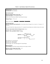
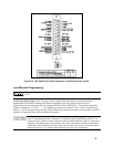
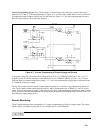
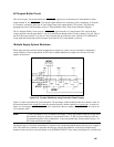
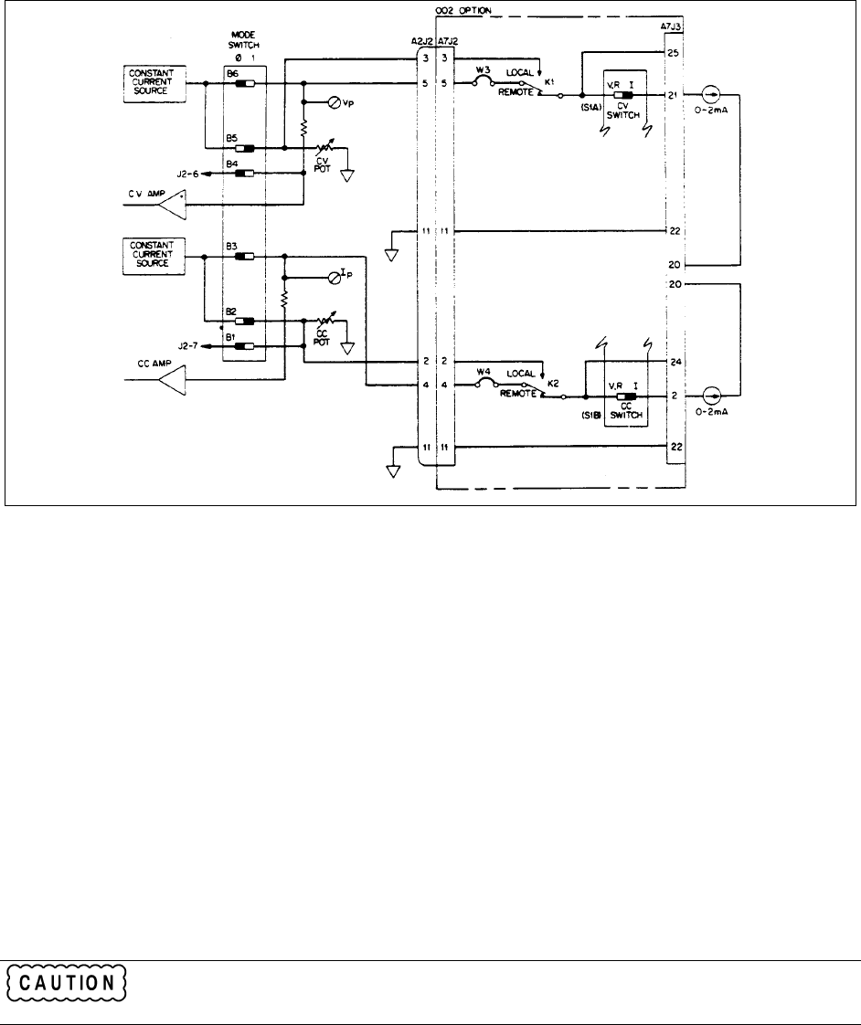
Current Programming (Figure A-7).
Check switches A1 and A2 on the rear panel, they must be in the correct
positions for CV and CC current programming (see Figure A-2). A current sink variable from 0 to 2mA, can be used
to program the output voltage or current from 0 to full scale (see Figure A-7). The following paragraph provides a
brief circuit description, refer to schematic diagram.
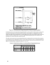
Figure A-7. Current Programming of Output Voltage and Current
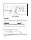
To program voltage, the current sink can be connected from J3-21 (CV CURRENT PROG) to J3-20 ( -15V). To
program current, the current sink can be connected from J3-2 (CC CURRENT PROG) to J3-20 ( -15V). Current
sinks can either be connected to the power supply ( -15 V) or to an external negative supply that is referenced to the
L. COMMON of the power supply.
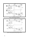
The 0 to 2mA current sink will cause the output signal of op-amps U17 and U18 to vary proportionally from 0 to 5
volts. These signals are then coupled through relays K1 and K2 and then on to the A2 Board's CV and CC circuits
which, in-turn, will program the supply's output from 0 to full scale. If the programming lines become open circuited
(user's system becomes disconnected from J3) during current programming, the Programming Protection circuit will
bring the power supply output to zero.
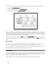
Remote Monitoring
The 002 Option board provides a protected 0 to 5V output corresponding to a full scale voltage output. The voltage
monitor output is available between pins J3-5 (V. Monitor) and J3-1 (D COMMON).
Observe the caution described in Local Programming (Figure A-3) paragraph, page 96.