


45
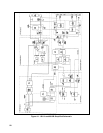
Circuits Included.
Constant Current (CC) Circuit on A2 control board.
Setup. The Main Troubleshooting Setup, page 33, except connect the external supply with polarity reversed to the unit's +
OUT ( - ) and - OUT ( + ) terminals. Apply the ac mains voltage to the isolation transformer. Set the external supply to
3.0Adc constant current with a voltage limit in the range 5 to 20Vdc. Set mode switches B1, B2 and B3 to 0. Set IP to 0Vdc
by connecting to
P or set IP to + 5Vdc by connecting to A2J7-24 according to SETUP below.
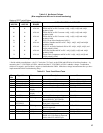
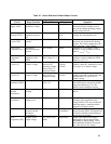
Outputs:
NODE ( + ) NODE ( - ) SETUP MEASUREMENT
IM A2J7-4 IP = 5 (6015A) 0.125Vdc (0.88Vdc, 6015A)
A2U4-8 A2J7-4 IP = 0 -14Vdc
A2U4-8 A2J7-4 IP = 5 +14Vdc
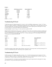
If the failure symptoms include output current oscillation, check if the differentiator circuit is at fault by removing resistor
A2R35 ( 1M ohm) (3.3M ohm, 6011A). If oscillations stop, the differentiator is probably at fault.
Troubleshooting OVP Circuit
Flip-flop A2U8A-A2U8D is set by comparator A2U8C and reset by PCLR . TTL low at A2U18-12 inhibits the PWM.
OVP Program Voltage on A2J7-7 is equal to Eout/10.
Circuit included. OVP Circuit and 2.5V bias supply on A2 control board.
Setup. The Main Troubleshooting Setup, page 33, except connect the external supply to the unit's + OUT ( + ) and - OUT
( - ) terminals. Apply the ac mains voltage to the isolation transformer. Adjust the unit's OVP limit to 10Vdc. Set the
external supply (EXTERNAL) as instructed below.
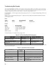
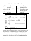
Outputs:
NODE ( - ) = A2J7-4
NODE ( + ) SET VOLTAGE
EXTERNAL (Vdc)
SETUP MEASUREMENT
A2U7-2 - 2.5Vdc
A2J7-7 - 1.0Vdc
≈2.2Vdc (6015A)*
A2J7-13 5 hi
A2J7-13 15 lo
A2J7-13 5 lo
A2J7-13 5 cycle power hi
* Front panel OVP control turned fully cw.
Note Connecting a test probe to either input of either comparator in the OV Flip flop (pins A2U8-1, 6, 7, 10, 11
or 13) may cause the flip flop to change states and cause the probed input to be low.